 Home
HomeWall friction test
Description
This text describes how to calibrate the particle-wall friction coefficients using a ring shear tester. For more information about the setup, please refer to Schulze.
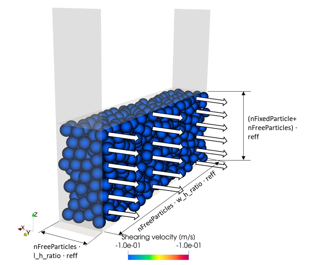
Figure 1: Simulation result of wall friction test obtained from the
wallFrictionTest tutorial.
Introduction
The friction between particles and solid surfaces plays an important
role in silos, chutes and other systems where the granular material
flows across a wall. The wall friction test consists of compressing
a granular material sample normally to a wall a shifting it with constant
velocity parallel to the wall. For each normal stress, the steady-state
tangential shear stress acting between sample and wall is measured. The
pair of values  form the so-called wall
yield locus.
form the so-called wall
yield locus.
The wall friction test can be performed using a ring shear tester, where a thin layer of granular material (typically between 5 and 10 mm) is sheared against a surface of the same material of the target wall. The lid of the cell is designed to shift the powder sample and to minimize the straining. In this tutorial, the particle-wall (p-w) static and rolling friction coefficients are calibrated using the shear cell test operating in wall friction mode (i.e., wall_mode = 1). The powder is assumed to be non-cohesive: in case of cohesive powders, it might be necessary to calibrate also the particle-wall coefficients of the cohesion model.
Detailed descriptions
Contact model and coarsegraining factor
The contact model and the coarsegraining factor are defined
in the file settings/contact_model.txt.
The models used in this tutorial are:
Hertz normal, tangential history,
rolling friction epsd2. The
cohesion model is switched off and the surface model is set to default.
More information about the contact models allowed by the templates
can be found in the shear cell test
documentation. The calibration simulations are performed without
coarsegraining (i.e., coarsegraining factor = 1).
Material properties and particle size distribution
The values of the fixed material parameters and the initial, minimum and
maximum values of the target material parameters are defined in
the file settings/materials.txt. The calibration template considers
both the bottom and lateral walls being of the same material.
The particle size distribution is defined in the file
settings/particle_sizes.txt.
Calibration case settings
The tutorial consists of a single calibration_case of the
template shear cell test.
Some template-specific settings of the calibration case are defined in the
file settings/tests.txt.
Experience showed that a number of fixed and free particles (n_fix_part and
n_free_part) equal to 4 is sufficient to reproduce satisfactorily
the experimental results. When using the wall friction mode, both fixed and free
particles are translated with a constant shearing velocity in the x direction, while
the top wall compresses them against the bottom wall. Futhermore, the volume enclosing the free
particles should have the same lateral aspect-ratio (w_h_ratio) as the sample in the
experimental setup; see Figure 1.
Other more general settings, like the number of iterations of the calibration
procedure, can be found in the file settings/general.txt.
Running the tutorial and analyzing the results
The user can run the tutorial via command line as follows:
aspherix-calibration run -in wall_friction_test.casx
The convergence of the calibration is reported in the file
calibration/results/conv.dat, which reads as follows:
# nIter       c_frict_pw   c_rollFrict_pw         qf_total
      1            0.375            0.375          3713.62
      3         0.158333            0.375          1462.98
      6         0.158333         0.591667          1462.92
     10         0.230556         0.591667           258.18
     16         0.230556            0.375          258.079
The iteration returning the lowest value of the quality function is the number 16. The comparison between the reference and the simulated wall yield locus is shown in Figure 2.
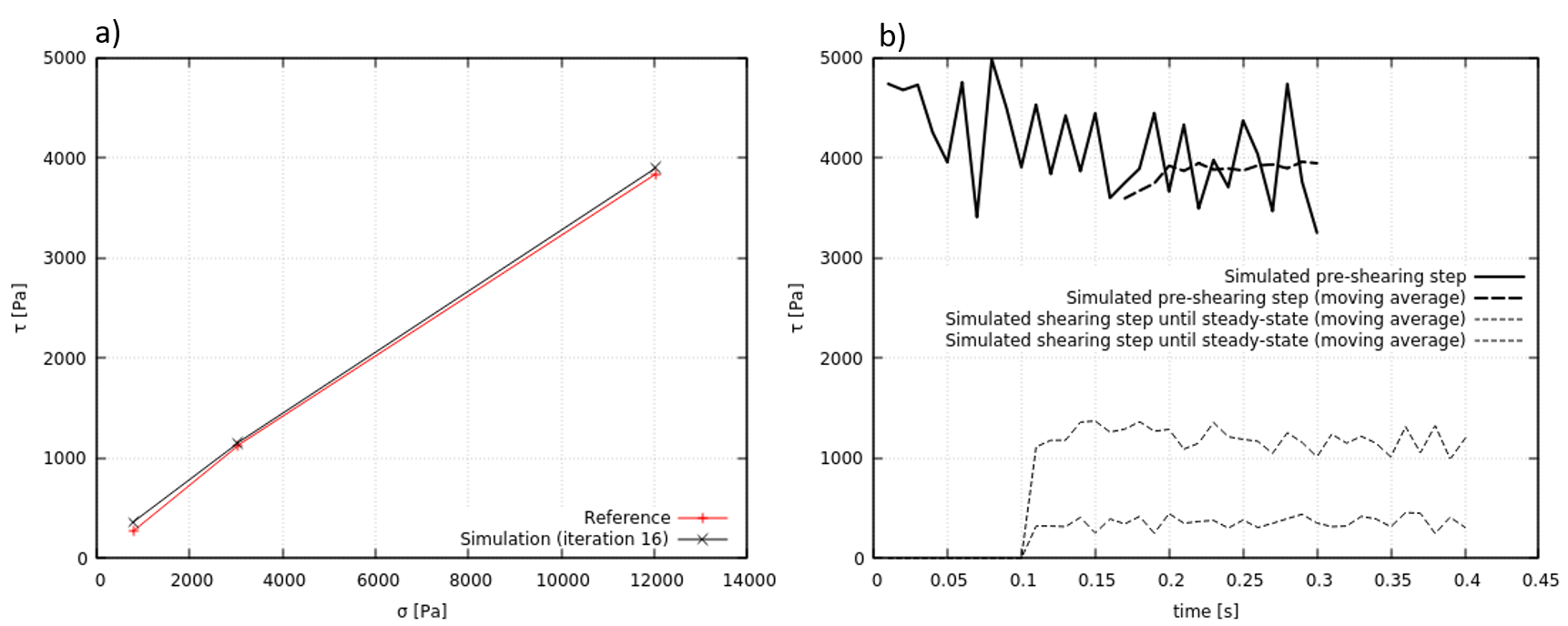
Figure 2: a) wall yield locus (reference and simulation), b) tangential shear
stresses at pre-shearing and shearing until steady-state obtained from the
simulation. The curves in a) can be plotted using the output files
simulation_results.txt and reference.txt in the folder
calibration/workDir/workDir.16/Aspherix/test1. The curves in b) can be
plotted using the output files in calibration/workDir/workDir.16/Aspherix/test1/data.
In summary, the result of the calibration consists of the following 2 parameters:
c_frict_pw = 0.230556
c_rollFrict_pw = 0.375
Warning
Different values of the calibrated parameters migh be obtained in serial versus parallel calibrations. This is caused by the insertion algorithm (packing generator simple) used in the initialization phase: the configuration of the resulting particle bed depends on the number of processors. This effect might be attenuated by increasing the number of particles.
Warning
It was verified that the wall yield locus, i.e. the quantity that the DEM simulation aims to reproduce in this tutorial, is not very sensitive to variations of the particle-wall coefficient of rolling friction, and that the dominat parameter is the particle-wall static coefficient of friction. Thus, we recommend the Inclination Test for calibration of the particle-wall coefficient of rolling friction.
Literature
[1] Schulze, D. “Flow properties of bulk solids.” Powders and Bulk Solids. Springer, Cham, 2021. 57-100.