 Home
HomeshearCellSchulzePeriodic
Overview
Template Info
- Target Parameters: c_frict_xx c_rollingFrict_xx cohStrength_pp maxCohStress_pp cohEnDens_pp cohEnSurfDens_pp cohEnSurfDens_pw
- Contact Models: tangential no_history tangential history cohesion adaptive rolling_friction epsd2 cohesion sjkr cohesion sjkr2 cohesion jkr/general
- Particle Shapes: sphere
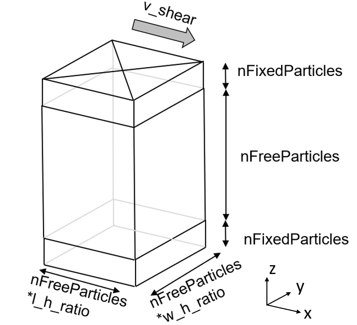
This case simulates a Schulze shear ring test. The setup consists of a rectangular box filled with particles, which is loaded with a normal stress in the z-direction and a shear stress in the x-direction. The box is periodic in the shear direction to simulate an infinite particle layer.
This case can be used to calibrate both the particle-particle and
particle-wall static friction coefficient, namely c_frict_pp
and c_frict_pw. In case of cohesive powders, the cohesion model
coefficients can be also calibrated. For the adaptive
cohesion model, the particle-particle cohesion strength and maximum
cohesion stress can be calibrated by setting cohStrength_pp and
maxCohStress_exp_pp to target parameters.
Note
In this template, maxCohStress_exp_xx is defined as  (
(maxCohStress_xx).
Simulation phases
Initialization
The domain is filled with particles and then cut so that the required
height  is reached, where
  is the thickness of the bottom and top layers and
  is the
thickness of the bulk; see figure above. If
is the
thickness of the bulk; see figure above. If wall_mode is set to 0, the bottom
layer of particles is kept fixed, whereas if set to 1, the bottom particles
are left free to move.
A first pre-shearing takes place during the initialization. The
normal_stress_shear_pre stress and the shear_velocity are imposed
on the top particle layer. The duration of the pre-shearing phase is
determined as follows:
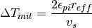
where  and
and  correspond to the setting parameters
 target_strain_pre_stress_init
and shear_velocity. In order for the stresses to reach a
steady-state condition, target_strain_pre_stress_init has to be
chosen large enough. Experience shows that a value of 100 is conservative
enough. The particle configuration is saved to a restart file at the
end of the pre-shearing phase.
Note
In case the particle-wall friction coefficients are to be calibrated,
it is advised to set wall_mode to 1.
Optimization
At the beginning of the optimization phase, the particle configuration
generated during the initialization is loaded and the up-to-date values
of the target parameters are imposed. Since these coefficients are subject
to calibration and, in general, they are different from the ones used
during the initialization, a transitory simulation is run. The
normal_stress_shear_pre stress and the shear_velocity are once again
imposed on the top particle layer, while the average tangential stress
is periodically measured. The duration of the transitory phase is
determined as follows:
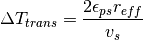
where  corresponds to the setting parameter
target_strain_pre_stress. In order for the stresses to reach a
steady-state condition, target_strain_pre_stress has to be
chosen large enough. Experience shows that a value of 80 is conservative
enough. The particle configuration is then saved to a restart file and
used for all subsequent stressing simulations. The steady-state value
of the shear stress is also recorded.
After the transitory phase, a simulation is run for each
normal_stress_shear following the normal_stress_shear_pre. The
particle state is first loaded, then the normal stress on the top particle
layer is gradually decreased from the normal_stress_shear_pre to
normal_stress_shear, and finally the shear_velocity is imposed on
the top particle layer in the opposite direction with respect to the
pre-shearing. The simulation is run until the shear stress reaches a
peak or the following maximum duration is reached
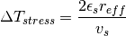
where  corresponds to the setting parameter
target_strain_stress. In order to capture the shear stress peak,
target_strain_stress has to be chosen large enough. The
optimal value depends strongly on the case; hence, it is advisable to
test two different values and see if the results change. If the peak
is correctly captured in both cases, then the calibration results should
be the same. Experience shows that a value of 40 is conservative enough.
Finally, the maximum shear stress is recorded and the simulation is terminated.
Quality function
The quality function computes the difference between the simulated and reference yield loci (including the pre-shearing points):
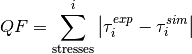
However, this can be problematic in case of high pre-shear normal stress and low
normal stress during shearing. With normalize_qf_to_normal_stress 1, the
differences in shear stress are normalized to the corresponding normal stress
before summation:
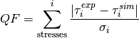
The measurement file must contain a list of normal and shear stresses in a comma separated list and two header lines. An example can be seen below:
# failure points of shear cells, format:
# sigma, tau
1234, 974
495, 103
823, 506
Note, Aspherix® Calibration will match the normal stresses in the input script with those in the measurement file. It is the responsibility of the user to ensure that the normal stress for pre-shearing is the largest normal stress in the file. Generally, when using this calibration case it is not necessary to use all failure points that are generated from a shear cell. What we found to be useful is to use two shear values together with the mandatory pre_shear value for one parameter and if another parameter was calibrated two different shear values if enough failure points were available from the experimental data set.
Tutorial documentation
The Cohesive powder calibration tutorial describes an application of this template.
Template parameters
General settings
Parameter |
Default |
|---|---|
scaleweight |
1 |
pairGranModel |
hertz |
pairTangential |
history |
pairCohesion |
adaptive |
pairRollingFriction |
epsd2 |
pairSurface |
default |
NPROC |
4 |
dumpT |
0.01 s |
dump |
1 |
Specific settings
Variable |
Default |
Meaning [units] |
|---|---|---|
torsionTorque |
on |
Affects only the rolling friction model; see gran_rolling_friction_epsd2 |
tangential_damping |
off |
See jkr/general |
create_bonds_at_timestep |
off |
See jkr/general |
disable_cohesion_for_unbonded |
off |
See jkr/general |
break_at_max_force |
off |
See jkr/general |
disableNormalWhenBonded |
off |
See jkr/general |
w_h_ratio |
1.25 |
Ratio between width and height of shear cell [] |
l_h_ratio |
0.5 |
Ratio between length and height of shear cell [] |
normal_stress_shear_pre |
1542 |
Value of the normal stress during pre-shearing [Pa] |
normal_stress_shear_1 |
365 |
Value of first normal stress during shearing [Pa] |
normal_stress_shear_2, …, normal_stress_shear_10 |
-1 |
Values of the 2nd to 10th normal stresses during shearing [Pa] |
normalize_qf_to_normal_stress |
0 |
Enable/disable normalization of shear stress differences in quality function |
shear_velocity |
0.01 |
Shear velocity [m/s] |
nFixedParticles |
2 |
Number of fixed particles on top and bottom, respectively in z-direction [] |
nFreeParticles |
40 |
Number of free particles in z-direction, indicates number of particles used to resolve the shear band [] |
target_strain_pre_stress_init |
100 |
Maximum shear deformation of the sample during pre-shearing (initialization phase) [particle diameters] |
target_strain_pre_stress |
80 |
Maximum shear deformation of the sample during transitory (optimization phase) [particle diameters] |
target_strain_stress |
40 |
Maximum shear deformation of the sample after transitory (optimization phase) [particle diameters] |
wall_mode |
0 |
Switch to enable/disable wall friction calibration |
freeze_particle_rotation |
0 |
Switch to block particle rotation |
reff |
-1 |
effective radius, used to compute all dimensions of the shear cell (if <= 0: maximum radius is used) [m] |
si_units |
1 |
Units (1 = si, 0 = cgs) |
binning_type |
monodisperse_binning |
Binning type in neighborlist algorithm |
max_neighbors |
2000 |
Correspond to the keyword “one” of the neigh_modify command |
max_page |
100000 |
Correspond to the keyword “page” of the neigh_modify command |
The
w_h_rationeeds to be the same as in the experiment. Experience has shown that geometric similarity of the shear cell crossection between experiment and simulation is crucial to obtain accurate calibration results.A value of 40 for
nFreeParticleshas been found to work well for cohesive material. For non-cohesive materials, a lower value (20-30) might work, depending on the details of the material. Note that doubling this value will increase the simulation by a factor of eight!reffis by default equal to the largest radius present. For highly polydisperse systems with large ratios between maximum and minimum radius, it might be beneficial to lowerreffto reduce the number of particles and keep computational demand in control. If the user decides to impose a value forreffdifferent from the default one, the following condition has to be satisfied:rmin<=reff<=rmax, otherwisereffis capped automatically torminandrmax.freeze_particle_rotationis generally set to 0. Sometimes the slope of the reference yield locus is so high that cannot be reproduced even by the cohesion model. This might be caused by highly non-spherical particles such as needle-like crystals with high aspect-ratio. If this is the case, experience showed that settingfreeze_particle_rotationequal to 1 allows the calibration of the static friction and/or cohesion coefficients and a good matching of the reference yield locus. Note that the calibration of the rolling friction coefficient loses any meaning forfreeze_particle_rotation 1and should be avoided. Additional experiments (e.g., inclined plane or static angle of repose) might be required to calibrate the rolling friction coefficient.When calibrating the rolling and/or static friction coefficient between particle and a wall material (i.e.,
wall_mode = 1), be aware that: 1) the number of free particles must be sufficiently low to avoid shearing in the layer (e.g.,nFreeParticles≈nFixedParticles). This means, that the entire particle layer must be dragged by the top lid so that it can slip on the bottom wall. The material of the bottom and lateral walls is the same and it represents the target wall material for the calibration. 2) The simulated wall yield locus is calculated based on the steady-state value of the wall shear stress for different normal stresses; hence, the reference yield locus provided by the user needs to be consistently a wall yield locus (please, refer to Schulze for more information).
Note
The parameter torsionTorque affects the rolling friction model. Please,
refer to gran_rolling_friction_epsd2
for more information.
Note
The parameters create_bonds_at_timestep,
disable_cohesion_for_unbonded, break_at_max_force and disableNormalWhenBonded
refer to the specific settings of the jkr/general
model.
Note
In case of small non-coarsegrained particles (of the order of the micron),
it is necessary to set si_units to 0 (see documentation).
In case of highly polydisperse system, it is necessary to set binning_type to
polydisperse_binning (see documentation).
Note
The max_neighbors and max_page options affect how memory is allocated for the
neighbor lists. They correspond to the keywords one and page of the neigh_modify command
command.
Literature
[1] Schulze, Dietmar. “Powders and bulk solids.” Behaviour, characterization, storage and flow. Springer 22 (2008).