 Home
HomesolidDeformationWithBonds
Overview
Template Info
- Target Parameters: nBondStiffpUA tBondStiffpUA rMulBond
- Contact Models: cohesion bond
This case is used to calibrate the elastic properties (Young’s modulus, Poisson’s ratio) of an elastic particle made from bonded primary particles. The particle is defined via a template as explained here. More information on the bond model can be found here.
This case is sensitive to three target parameters, given in the table below:
|
normal bond stiffness per unit area [Pa/m^3] |
|
tangential bond stiffness per unit area [Pa/m^3] |
|
bond radius multiplier [-] |
Example
calibration_case compressionTest template solidDeformationWithBonds type Aspherix &
    target_param nBondStiffpUA tBondStiffpUA rMulBond &
    measfile measurements/force.txt &
    dem_timestep 1e-7 &
    parameter_overrides &
    maxRelCompression 0.3 &
    spheresFile data/mySpheres.csv &
    templateScaleFactor 0.1 &
    compressionPreFactor 1. &
    forcePreFactor 1e-3 &
    createDistanceRel 1.5 &
    maxDistanceRel 2.5
Simulation phases
Initialization
This case does not do anything during initialization.
Optimization
In the simulation, the ellipsoidal particle is compressed between two
square meshes. The user has to specify the layout of such a particle
in a file following the format documented in the solver
documentation (section ‘bonded’). The path
to this file relative to the main calibration directory must be
passed via param_modify spheresFile [path/to/file].
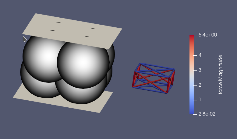
The image below shows a snapshot of a simulation. On top, the particle and the two plates are shown, and the primary particles are colored by ID. On bottom, the bond network is displayed, colored by bond force.
Due to its simplicity, the case is always created from scratch. A
particle is inserted between the two square meshes, and the upper mesh
moves down with a defined velocity to compress the particle. The case
is run until a defined maximum relative compression (see
maxRelCompression above) is reached. Relative displacement, force
on the mesh and relative lateral expansion are written to a file named
force.txt.
Quality Function
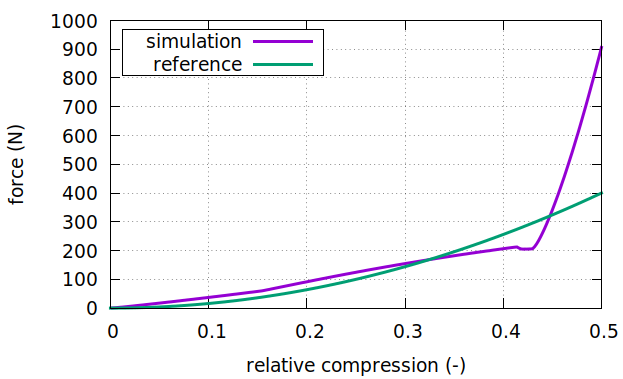
The quality function is computed as the curve distance between the reference force curve and the simulation results.
Measurement data
This calibration case expects comma- or space separated data (format: see here) with the relative compression in the first column, and the force in Newton in the second column. The relative compression is defined as
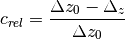
where  is the distance between the two meshes, and
 is their initial distance. Other colums, if
present, are ignored. Both the relative compression and the force from
the reference data can be scaled via the
is their initial distance. Other colums, if
present, are ignored. Both the relative compression and the force from
the reference data can be scaled via the compressionPreFactor and
forcePreFactor settings if required. An example file could look
like
# relativeCompression[-] force[N]
0.000000 0.000000
0.001002 0.001606
0.002004 0.006426
0.003006 0.014458
0.004008 0.025703
Template parameters
General settings
Parameter |
Default |
|---|---|
scaleweight |
1 |
dumpT |
0.01 s |
dump |
0 |
Note
This case is too small for reasonable parallelization, and
therefore the setting NPROC that is available in other
calibration case templates has no effect (the simulation is
executed without MPI).
Specific settings
The case template accepts the following variables to modify the behaviour of the case:
Variable |
Default Value |
Meaning |
|---|---|---|
spheresFile |
undefined |
path to the particle template relative to the calibration directory |
templateScaleFactor |
1 |
scaling factor for the template |
vMesh |
0.01 |
velocity of the top mesh [m/s] |
maxRelCompression |
0.5 |
relative compression until which the simulation is run. Must be between 0 and 1. [-] |
compressionPreFactor |
1 |
scaling factor for the relative compression in the reference data [-] |
forcePreFactor |
1 |
scaling factor for the force in the reference data [-] |
createDistRel |
1.01 |
Relative distance for bond creation |
maxDistRel |
3 |
Maximum distance for bonds |
Most of these settings are self-explanatory, but the last two require
some explanation. When the bonded particle is inserted, Aspherix®
needs to decide whether to create bonds between particles. This is
controlled by the createDistRel parameter: a bond between
particles is created when

where  is the center distance between the two particles,
and
is the center distance between the two particles,
and  are their radii. This setting will influence the
number of bonds in your particle, and thus its mechanical properties
(simply speaking: more bonds –> more rigid particle). A bond also has
a maximum distance, which is set via the
are their radii. This setting will influence the
number of bonds in your particle, and thus its mechanical properties
(simply speaking: more bonds –> more rigid particle). A bond also has
a maximum distance, which is set via the maxDistRel setting. A
bond is disabled if

More details can be found in the solver documentation for the bond model. Other methods for bond creation and breakage are currently not supported by this template.