 Home
HomerotatingDrum
Overview
Template Info
- Target Parameters: c_frict_xx c_rollingFrict_xx initCohStress_xx maxCohesiveStress_xx cohStrength_xx cohEnDens_xx
- Contact Models: tangential no_history tangential history rolling_friction off rolling_friction epsd rolling_friction epsd2 cohesion off cohesion adaptive cohesion sjkr cohesion sjkr2
- Particle Shapes: sphere multisphere
This calibration template simulates a rotating drum that is scalable in both depth and diameter. The template is very similar to the GranuDrum template, but offers more options for configuration.
This setup is designed to be sensitive to the particle-particle static/rolling
friction and cohesion coefficients. Hence, one or more of these target
parameters can be iteratively modified during the calibration process to achieve
the optimal correspondence between simulation and reference results. To
calibrate friction, set c_frict_pp and/or c_rollFrict_pp as target
parameters. For cohesion, the adaptive,
the simplified jkr, and the
modified sjkr models are supported.
To calibrate the adaptive model, the user is invited to select the
maxCohStress_exp_pp and the cohStrength_pp as target parameters, while
to calibrate the sjkr and sjkr2 models, the user it invited to select
the cohEnDens_pp as target parameter. Here, it should be specified that
maxCohStress_exp_xx is equal to the logarithm of the maximum cohesive stress
as defined in the adaptive model (i.e.,
maxCohStress_exp_pp = 2 corresponds to maxCohesiveStress_pp = 10^2).
The parameters initCohStress_pp and initCohStress_pw of the adaptive
model are typically set to zero; hence, they are rarely calibrated. The calibration of the
particle-wall interaction parameters such as c_frict_pw, c_rollFrict_pw,
maxCohStress_exp_pw, cohStrength_pw and cohEnDens_pw is possible
as well; however, other tests might be better suited to calibrate them, like for
example the inclination test and the
wall friction test.
It is possible to calibrate cohesion and friction at the same time. Note that this will increase the parameter space and hence the number of simulations required to obtain a properly calibrated parameter set.
The load balancing is disabled by default
due to the non-deterministic nature of the algorithm which can effect the
results of calibration. If the number of particles is sufficiently high ( and above), the non-deterministic effect induced by the load balancing algorithm
is negligible and load balancing should be enabled by setting the
parameter
and above), the non-deterministic effect induced by the load balancing algorithm
is negligible and load balancing should be enabled by setting the
parameter useLoadBalancing to 1. Be aware that the load balancing can substantially
speed-up the calibration process.
Simulation phases
Filling
During this phase, particles are inserted into the drum. The
amount of particles depends on the desired filling level,
which can specified through the fillLevel variable.
Settling
During this phase, the inserted particles settle down. The simulation stops when the total kinetic energy is below a certain threshold.
Rotation
During this phase, the drum is rotated. Rotation starts instantaneously, but
measurement will only commence after a time interval of simEquilTime has
passed. The simulation then continues for a period speicfied through
simMeasTime, during which images of the simulation are being written. The
time interval for writing is specified through dumpT.
Note
It is recommended to use at least one quarter of the rotation period (or
 ) for both
 simEquilTime and
simMeasTime.
Quality function
The images of the granular material obtained from the simulations during the
rotation phase are used to calculate the average interface position and the
dynamic cohesive index, where the latter is defined as the standard deviation
of the interface position; see Neveu et al.. From the average
interface position, the average dynamic angle of repose is computed as the
inclination of the slope between two points. These points can be defined via
measWindowLeft and measWindowRight. Both values are given in fractions
of the radius, and indicate a signed distance from the rotation axis. So, for
example, a value of -0.2 for measWindowLeft means that the left point lies
 left of the axis, and a value of 0.3 for
 measWindowRight
puts the right point at  right of the axis.
The quality function is calculated as follows:

where  and
and  are the simulated
and reference dynamic angle of repose,
are the simulated
and reference dynamic angle of repose,  and
and  are the simulated and reference dynamic cohesive index, and
  is
a weight factor for modulating the contribution of the dynamic cohesive index
to the quality function. The factor , which by default is equal to zero,
can be defined using the keyword
is
a weight factor for modulating the contribution of the dynamic cohesive index
to the quality function. The factor , which by default is equal to zero,
can be defined using the keyword cohesiveIndexWeight.
Measurement file
The measurement file can contain:
both the average dynamic of angle of repose and the dynamic cohesive index, or
the average dynamic of angle of repose alone, or
the path to the images of the rotating drum
Here are some examples of potential measurement files:
angle=62.34
cohesive_index=20.0
angle=62.34
image_path=path/to/image/directory
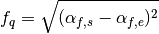
By specifying the average dynamic of angle of repose alone, the quality function is calulated as follows:
In case the path to the images of the rotating drum is specified, Aspherix® Calibration loads all .png files in the given folder and computes both the average dynamic of angle of repose and the dynamic cohesive index from those images. In order to be usable, the images require some pre-processing. Below is a typical image from a rotating drum measurement:
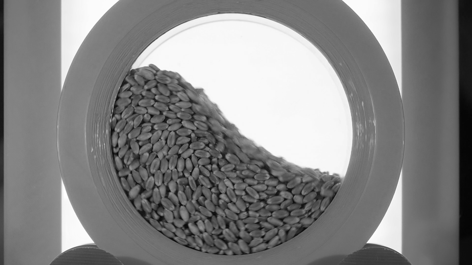
The final image to be used needs to
be square (same amount of pixels in width and height) and depict exactly the whole rotating drum (assumption: the width/height in pixel is exactly the drum diameter)
have a black background. The angle of repose is extracted from non-black pixels
have high contrast
A processed image could look like the one below:
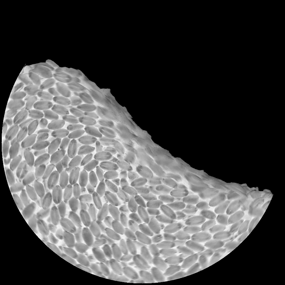
The processing was performed using this python script:
#! /usr/bin/python3

import cv2 as cv
import numpy as np
import argparse
import glob
import os

parser = argparse.ArgumentParser()
parser.add_argument("directory")
parser.add_argument("--xlo",type=int)
parser.add_argument("--ylo",type=int)
parser.add_argument("--dx",type=int)
parser.add_argument("--radius-offset",type=int)
parser.add_argument("--threshold",type=int)

args = parser.parse_args()

xlo = args.xlo
ylo = args.ylo
dx = args.dx
r = int(dx/2)-args.radius_offset
cx = xlo+r+1
cy = ylo+r+1
threshold = args.threshold

srcdir = args.directory
destdir = os.path.join(srcdir,"processed")

for f in glob.glob(os.path.join(srcdir,"*gs*.png")):
    infile = f
    outfile = os.path.join(destdir,os.path.basename(infile))
    img = cv.imread(infile)
    img_crop = img[xlo:xlo+dx, ylo:ylo+dx]
    img_inv = cv.bitwise_not(img_crop, img_crop)
    mask = np.zeros((img_crop.shape[0],img_crop.shape[1]),np.uint8)
    circle_mask = cv.circle(mask,(int(dx/2),int(dx/2)),r,(255,255,255),thickness=-1)
    img_masked = cv.bitwise_and(img_inv, img_inv, mask=circle_mask)
    ret,img_thresh = cv.threshold(img_masked,threshold,255,cv.THRESH_TOZERO)
    cv.imwrite(outfile,img_thresh)
which was called with the parameters
./convert.py --xlo 56 --ylo 448 --dx 981 --radius-offset 5 --threshold 70 path/to/image/dir
Template parameters
General settings
Parameter |
Default |
|---|---|
scaleweight |
1 |
pairGranModel |
hertz |
pairTangential |
history |
pairCohesion |
sjkr |
pairRollingFriction |
epsd |
torsionTorque |
on |
pairSurface |
default |
NPROC |
4 |
dumpT |
0.01 s |
dump |
0 |
nChunks |
1 |
coresPerChunk |
1 |
useLoadBalancing |
0 |
Specific settings
Variable |
Default |
Meaning |
|---|---|---|
simEquilTime |
0.5 |
Interval of time [s] after reaching the prescribed rotation velocity. Needs to be large enough for the system to reach an equilibrium state. |
simMeasTime |
2 |
Interval of time [s] during which the images of the granular material are taken. |
RPMMeas |
undefined |
Rotations per minute used in the experiment |
fillLevel |
0.5 |
Fraction of the drum volume to be filled with particles. 0.5 corresponds to a half-full drum. Values higher than 0.5 are not recommended due to limitations of particle insertion. [-] |
measWindowLeft |
-0.2 |
Left boundary of the measurement window for the dynamic angle of repose. Given as a fraction of the radius, where negative numbers indicate left from the center and positive numbers indicate right of the center. [-] |
measWindowRight |
0.2 |
Left and right boundaries of the measurment window for the measurement of the dynamic angle (see above) [-] |
cohesiveIndexWeight |
1 |
Weight for the calculation of the quality function [-] |
drumLength |
undefined |
axial lenght of the drum [m] |
drumRadius |
undefined |
radius of the drum [m] |
Literature
[1] Neveu, A., Francqui, F., & Lumay, G. (2022). Measuring powder flow properties in a rotating drum. Measurement, 200, 111548.