 Home
HomeuniaxialCompression
Overview
Template Info
- Target Parameters: cohesionEnergyDensity cohesionVariation cohesionStrength pullOffForce adhesionEnergy stiffnessRatio springPowerValue adhesionPowerValue
- Contact Models: tangential no_history tangential history rolling_friction epsd2 cohesion adaptive cohesion sjkr/powder normal adhesive_elasto_plastic tangential adhesive_elasto_plastic
- Particle Shapes: sphere
The uniaxial compression case simulates a confined/unconfined uniaxial compression of a powder, followed by unloading and yield test. This template can be used to calibrate either the powder compaction model with a cohesion model between the cohesion model adaptive and the cohesion model sjkr/powder, or the normal and tangential Edinburgh model.
The initial setup consists of a cylindrical container, when a confined system is selected, or a square box with periodic boundary conditions at the sides, when the unconfined system is selected; see sketch in the figure below. The container is filled with a certain mass of particles and a top lid compresses the system with a prescribed pressure. After the compression, the top lid is lifted and, in case of confined setup, the cylindrical walls are expanded.
In case of confined setup, the yield test consists of an additional compression of the powder sample without the surrounding cylinder. The yield test automatically stops when material failure is reached. In case of unconfined setup, the powder is compressed and sheared multiple times to obtained the yield locus. The yield pressure is than calculated based on the yield locus.
The load balancing is disabled by default
due to the non-deterministic nature of the algorithm which can effect the
results of calibration. If the number of particles is sufficiently high ( and above), the non-deterministic effect induced by the load balancing algorithm
is negligible and load balancing should be enabled by setting the
parameter
and above), the non-deterministic effect induced by the load balancing algorithm
is negligible and load balancing should be enabled by setting the
parameter useLoadBalancing to 1.
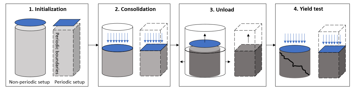
Simulation phases
Insertion
In this phase, the container is filled with spherical particles. The
amount of particles to be inserted (specified in the input script via
the mass keyword) is bounded by the heigth of the particle column
(specified in the input script via the keyword zmax) and the density
of the material (i.e., the density of the particles specified in the
particle distribution). If the following relation is not fullfilled,

where the 0.6 coefficient is an estimation of the packing density,
 ,
,  and
and  are respectively the mass of
inserted particles, the particle density and the volume of the insertion
region, then the combination of input is not consistent and the calibration
terminates with the following error:
are respectively the mass of
inserted particles, the particle density and the volume of the insertion
region, then the combination of input is not consistent and the calibration
terminates with the following error:
ERROR : calibration case case_name returned with exit status -3
where case_name is the generic user-assigned name for the calibration_case
command call. By inspecting the logfile calibration/simulations/Aspherix/case_name/logInit.txt,
the user can get more information about the initialization’s fail, including
a suggestion of the particle’s density that would lead to
the fulfillement of the relation above.
The periodic setup can be selected via the use_periodic_domain
keyword in the input script. By default, use_periodic_domain no, which
corresponds to the wall-confined setup. Regarding the dimensions of the
container, the diameter of the cylinder can be specified in the input script
via the keyword columnDiameter, while the lateral sizes of the square
box are automatically set equal to 30 times the particle diameter. This is done
to ensure a sufficient number of particles in the periodic directions. The
periodic case should be chosen for cases where the ratio of column diameter to
column height is large as we need to have sufficient particles in all
directions to resolve the physics and large aspect ratios can cause excessive
numbers of particles.
The simulation automatically stops when the particles have settled. This is achieved by monitoring their kinetic energy. The finished packing is then written to a restart file.
The insertion is performed only once before the calibration procedure.
Pre-consolidation
In this phase, the particle-filled container is loaded from the restart file and both the cohesion and compression powder models are enabled. The new dynamics perturbates the system and the simulation automatically stops when the particles have settled. This is achieved by monitoring their kinetic energy. The finished packing is then written to a restart file.
The cohesion models that can be choosen are two, namely the
cohesion model adaptive and the
cohesion model sjkr/powder; the
cohesion model can be specified via the pairCohesion keyword. By setting
pairCohesion to off, no cohesion model is selected.
Depending on the cohesion model, different material parameters need to be specified
in the input script. Please, refer to the material parameters
for more information about the required material parameters for the adaptive and
the sjkr/powder cohesion models. The parameter of the
fix powder/update command that should be used
as target parameters in the calibration procedure are: compressibility, dilatability,
hardening (if use_hardening base or use_hardening exponent) and compression_exponent
(if use_hardening base or use_hardening exponent and non_linear yes). The parameter
alpha_min should set as a fixed parameter for each setup
separately using the following value:
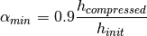
where  and
and  are the initial
(uncompressed) and minimum (fully compressed) height of column in the
experiment.
are the initial
(uncompressed) and minimum (fully compressed) height of column in the
experiment.
Additional fixed parameters of the fix powder/update command are:
alphaRelaxTime, pAvgTime, non_linear, use_hardening and
elastic_dilation. These have already assigned some default values; see
calibration input table at the end of the document. For detailed information
on their role in the compression powder model, please refer to the
Aspherix documentation.
The pre-consolidation is performed multiple times in the calibration procedure, as the model parameters might be also target parameters.
Consolidation
In this phase, the particles are compressed by a top lid until the pressure
specified in the input script by the max_pressure keyword is reached.
The lid can either move at constant velocity (this is the default setting,
i.e., piston_const_vel yes) or not (for piston_const_vel no). In this
second case, the lid behaves as a servo wall pushing downwards with the target
pressure. As a consequence, the lid will initially accelerate and then
gradually decelerate as the particle compression proceeds. At the equilibrium,
the particles will exert the same target pressure on the lid. This method
prevents pressure overshootings that might arise in case of a compression at
constant velocity. Please, be aware that piston_const_vel no might
sensibly increase the calibration duration and that the consolidation stage
might stall when very low values of max_pressure are used.
The simulation automatically stops when the average pressure of the particles on the lid corresponds to the target one and, in case of non-constant velocity, the lid does not move anymore. The resulting system is written to a restart file.
The consolidation is performed multiple times in the calibration procedure.
Unload
In this phase, the top lid and, in case of confined setup, the cylinder walls
move away from the particles. The cylinder walls can move after or at the same
time of the top lid. These behavious can be triggered by the moveCylAfterTop
keyword in the input script. If moveCylAfterTop 0, the cylinder is expanded
when the top plate moves up, while if moveCylAfterTop 1 (default value) the
cylinder walls move away only when a zero pressure is exerted on the top lid.
The size increase of the confining cylinder walls during the unloading is
expressed in terms of percentage of the original dimension via the
cylinderExpansionPercentage keyword. The time between two successive
expansion in expressed in terms of number of time steps via the unloadRelaxSteps
keyword.
The unload is performed multiple times in the calibration procedure and the resuting data is written to a restart file.
Yield test
The yield test is different in case of non-periodic and periodic setup. If
the yield pressure is less than zero, than the yield test does not take place
(by default, yield_pressure -1). If yield_pressure >= 0, the yield
test is simulated and the value yield_pressure becomes the reference
yield pressure with which the numerical result is compared.
In the non-periodic setup, the top lid compresses the particle sample at the
constant velocity specified by piston_vel until failure is reached. The
yield stess is then compared to the reference value yield_pressure. The
particles close to the top lid can be free to move or bounded to move only in
the vertical direction. The different behaviours can be triggered by the
freeze_tangential keyword, which by default is set to yes.
In the periodic setup, the top lid compresses the particle bed with the normal
stress defined by max_pressure (which is referred to as  ).
After that, the layer is sheared with a constant velocity of 0.1 m/s until a
critically consolidated state is achieved. The average tangential stress
).
After that, the layer is sheared with a constant velocity of 0.1 m/s until a
critically consolidated state is achieved. The average tangential stress
 at steady-state is measured. The first shearing is followed by
another compression stage, this time with normal stress equal to
at steady-state is measured. The first shearing is followed by
another compression stage, this time with normal stress equal to max_pressure/2
(which is referred to as  ), and then by a shearing until failure,
which returns the tangential stress
), and then by a shearing until failure,
which returns the tangential stress  . The two-points yield locus is
save to file and used to obtain the yield pressure following the formula:
. The two-points yield locus is
save to file and used to obtain the yield pressure following the formula:

where  is the slope of the
yield locus.
is the slope of the
yield locus.
Quality function
The quality functions for the consolidation and unloading phases are normally
calculated by comparing the experimental and simulated force-displacement curves
as they are (qf_data_matching 0). Another possibility is to calculate the
quality functions after the peaks of both experimental and simulated force-displacement
curves are matched (qf_data_matching 1). The second option is useful when
the calibration of the powder compaction model is reached iteratively through a series
of stages. As an example, the first calibration stage could aim at calibrating the
compressibility alone, while the hardening is fixed. In this case, it is suggested
to set qf_data_matching 1. During the second stage, as the hardening is calibrated
and the calibrated compressibility is fixed, qf_data_matching can be set equal to
0.
Furthermore, the comparison can be limited to some stages to the calibration
procedure via the qf_restriction keyword (by defauls, qf_parts none, other
possibilities include qf_parts consolidate, qf_parts unload and
qf_parts yield to limit the quality function calculation only to the
consolidate, unload and yield stages, respectively).
The quality functions for the consolidate and unloading stages are calculated as the mean-square deviation between the experimental and the simulatated displacement-force curves,

where  is the number of measured values (or time samples),
  and
and  are the measured and simulated resultante force of the particles
on the top lid for different vertical displacements of the lid
are the measured and simulated resultante force of the particles
on the top lid for different vertical displacements of the lid  .
The simulated consolidation-unloading curve can be found in the
.
The simulated consolidation-unloading curve can be found in the consolidation.csv
file in your respective workDir subdirectory.
The quality function for the yielding stage is calculated as the difference between
the simulated yield pressure and the reference value yield_pressure.
Measurement file
The text file containing the experimental consolidation-unloading curve must have two columns: one for the vertical displacement of the top lid (expressed in meters) and the other for the resultant force exerted from the particle on the lid (expressed in Newton). The data in each row should be either space-, tab- or comma-separated. An example of measurment file is given below.
#z[m]    F[N]
 5.99    0
 5.98    3.5
 ...     ...
 2.07    0
Template parameters
General settings
Parameter |
Default |
|---|---|
scaleweight |
1 |
pairGranModel |
hertz |
pairTangential |
history |
pairCohesion |
sjkr/powder |
pairRollingFriction |
epsd2 |
torsionTorque |
on |
pairSurface |
default |
useLoadBalancing |
0 |
Specific settings
Variable |
Default |
Meaning [units] |
|---|---|---|
use_periodic_domain |
no |
no = confined setup (cylinder), yes = unconfined setup (square box with periodic boundaries at the sides) |
mass |
undefined |
Particle’s mass inside the confined setup [kg] |
zmax |
undefined |
Fill height of the material before compaction in both confined and unconfined setups [m] |
columnDiameter |
10e-3 |
Diameter of the cylindrical container [m] |
max_pressure |
undefined |
Maximum pressure (in reference experiment) of the lid on the particles during consolidation [Pa] |
scaling_factor |
1e-2 |
Scaling factor of the maximum pressure in simulation (to reduce the time step) must be <= 1 [-] |
use_hardening |
no |
Determines the hardening model of the powder model. It allows |
non_linear |
no |
Whether or not the hardening model is used in the non-linear regime (only effective if |
elastic_dilation |
yes |
Whether or not the powder model allows elastic dilation |
pAvgTime |
1e-3 |
Pressure average time of the powder model [s] |
alphaRelaxTime |
1e-3 |
alpha relaxation time of the powder model [s] |
unloadRelaxSteps |
100 |
How many time-steps between each successive column enlargement during unloading (valid only for confined setup) [-] |
piston_vel |
0.1 |
Velocity of piston [m/s] |
piston_const_vel |
yes |
yes = piston moves with constant velocity, no = piston moves at most with piston_vel but tries to exactly reach the max_pressure (slower) |
yield_pressure |
-1 |
Reference yield stress. If negative no yield testing is performed. [Pa] |
freeze_tangential |
yes |
Determines whether or not particles close to the top are allowed to move in tangential direction during yield testing |
moveCylAfterTop |
1 |
no = cylinder expands during unloading, yes = cylinder expands after piston has zero force |
cylinderExpansionPercentage |
10 |
Expansion of the cylinder during unloading [%] (effective only for non-periodic boundary conditions) |
dumpT |
0.1 |
Time interval at which DEM fields are written to file [s] |
binning_type |
monodisperse_binning |
Binning type in neighborlist algorithm |
max_neighbors |
2000 |
Correspond to the keyword “one” of the neigh_modify command |
max_page |
100000 |
Correspond to the keyword “page” of the neigh_modify command |
qf_data_matching |
0 |
Determines whether or not the pressure-displacement curve from the simulation is peak matched to the experimental data |
qf_restriction |
none |
Options: ‘consolidate’, ‘unload’, ‘yield’ or ‘none’; determines which part of the simulation curve is used for the quality function calculation |
Note
In case of highly polydisperse system, it is necessary to set binning_type to polydisperse_binning (see documentation). The “max_neighbors” and “max_page” options affect how memory is allocated for the neighbor lists. They correspond to the keywords “one” and “page” of the neigh_modify command command.