 Home
HomeErgun test
In the Ergun test, the fluidization of a particle bed due to fluid flow from below is simulated. For a homogeneous inflow profile the pressure drop across the particle bed is known as a function of the fluid velocity, the Ergun equation:

Moreover, the particles fluidize at the minimum fluidization velocity:
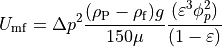
These two curves may be used as benchmark for the pressure at the bottom of the particle bed.
The current setup features a bulk inlet flow at the bottom and an outlet the top. The walls are treated as slip conditions. In a first step, particles are inserted into the domain to form a particle bed at the bottom. In a second step, the coupled simulation is started. The pressure drop is recorded as the difference between the pressure in the cells at the inlet and the outlet in the domain center. During the coupled simulation the inlet velocity is slowly increased to observe the pressure drop for different fluid velocities.
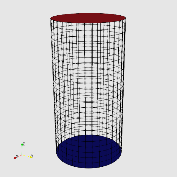
Figure 1: Sketch of the current setup with the fluid outlet at the top and the inlet at the bottom with the spout at the center highlighted.
The particular simulation discussed in this article is run with cfdemSolverPiso using spherical particles. There are numerous variations of this Ergun case for different solvers, model combinations, and particle shapes in the tutorials directory.
Note
This case is located in CFDEMcoupling/validationCases/ErgunTest_analytic.
Models used
Particle forces:
The drag force is computed by the Koch-Hill drag model.
Alteration of effective gravity forces due the difference of fluid and particle densities is modelled by the Archimedes force model.
Particles are mapped to CFD by the engine locateModel.
The voidfraction is computed by the divided voidfraction model.
Momentum exchange between particles and fluid is computed in an implicit manner, see Zhou et al. (2010), JFM.
Results
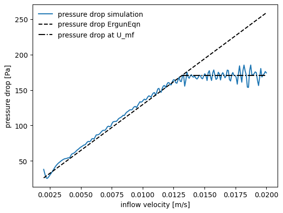

Figure 2: Resulting pressure drop over different inlet velocity values and comparison to the Ergun equation (left). The pressure drop only increases up to the onset of fluidization. The right image shows a snapshot of particle velocity and the pressure field at the end of the simulation.
Note
Run the case with the ./Autorun.sh script directly in the folder and select
the variant ErgunTest-piso. The initialization phase should take less than a minute.
The coupled simulation should finish in about the same amount of time.
Improvements
For cases with flow inlets directly into particle beds, impaired particle motion in the first cell downstream of the inlet is observed. To solve this issue, a correct pressure gradient must be provided in this cell, otherwise flow velocities are too low. Several options to resolve this issue are available:
Invert the inlet and outlet boundary conditions, i.e. set the velocity Dirichlet condition at the outlet and the pressure Dirichlet condition at the inlet. However, this set of boundary conditions may lead to an inhomogeneous inflow profile.
Move the patch for CFD inlet boundary condition side upstream by increasing the domain size of the flow simulation and, thus, separate the bottom of the particle bed from the flow inlet. Adding a porous zone to the flow below the particle bed may help in ensuring a homogeneous velocity profile at the bottom of the particle bed.
The recommended approach is to use cfdemSolverPimple with the following boundary conditions at the inlet:
voidfraction: zeroGradient (default BC)
pressure: fixedFluxExtrapolatedPressure
velocity: uniformFixedValueVoidfraction
Only solvers implementing the
PIMPLEprocedure (cfdemSolverPimple and similar solvers like cfdemSolverChem) – but not cfdemSolverPiso – properly correct for thefixedFluxExtrapolatedPressureboundary condition at the inlet. This condition should be preferred overfixedFluxPressurefor inlet conditions. To obtain the desired behavior, all three boundary conditions indicated above should be applied.Ergun test tutorial cases for solvers that support these boundary conditions also use this set of conditions at the inlet.
When using these boundary conditions, the results change slightly as demonstrated in Figure 3.
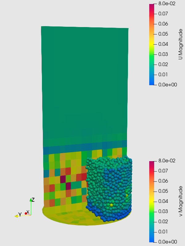
Figure 3: Fluid and particle velocity for standard setup simulated with cfdemSolverPiso (left) and the boundary conditions discussed above simulated with cfdemSolverPimple (right). The improved boundary conditions yield a continuous velocity field at the inlet and, moreover, improve the fluidization behavior of the particles directly at the inlet.
Note
The variants using cfdemSolverPimple is only avilable in the CFDEMcoupling-Premium package.