 Home
HomeSpout bed for different particle shapes
This tutorial presents a simulation setup similar to the Ergun test and Fluidization in a spout bed validation cases but emphasizes how to
extend the Ergun test with an additional spout
use different particle shapes
Note
This case is located in CFDEMcoupling/tutorials/cfdemSolverPiso/ErgunSpoutShapes.
Creating the spout
To create the spout
Select the cells using
topoSet, see the definition insystem/topoSetDictCreate a new patch using
createPatch -overwriteselected cells, see defintion insystem/createPatchDict. The-overwriteargument adds the new patch to the existing meshAdd boundary conditions for the new patch to all files in the initial solution
0
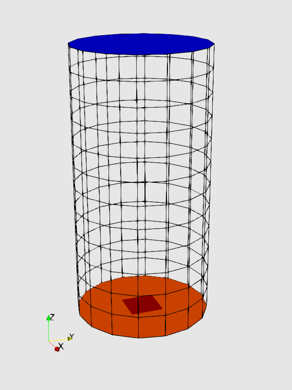
Figure 1: The resulting domain boundaries in the setup with the fluid outlet at the top and the inlet at the bottom. The spout at the center is highlighted in dark red.
Particle shapes
The particle shape is set on the DEM side using the particle_shape command and the setting for the particle_template command. On the CFD side there are two approaches:
Treat particles as (volume-equivalent) spheres:
In this case the DiFeliceDrag drag model is used regardless of the actual particle shape and the case setup does not differ for the different shapes. For multispheres the addtional setting
treat_multispheres_as_spheres yesis required for the enable_cfd_coupling command. These cases are run with cfdemSolverPiso which is available in all versions of CFDEM®coupling.Treat particles using shape-specific models:
More advanced options are available with solvers like cfdemSolverPisoNonspherical or cfdemSolverPimple using the
particleShapeTypekeyword inconstant/couplingProperties. These cases use more advanced drag model like HoelzerSommerfeldDrag and shape-specific variants of the dividedVoidFraction.
In addition to the discussed models, all cases use the Archimedes force model to account for the effective gravity forces due the difference of fluid and particle densities and the engine locateModel to map particles to the CFD cells. Momentum exchange between particles and fluid is computed in an implicit manner for all cases, see Theory of CFD-DEM.
Note
The DEM results are written into individual folders for each particles shape to circumvent results from being overwritten by furhter simulations for different shapes. The CFD results, however, are not trewated in a Similar manner.
Note
cfdemSolverPisoNonspherical, cfdemSolverPimple, further solvers with advanced integration of non-spherical particles, and corresponding models are available in the CFDEMcoupling-Premium package.
Results
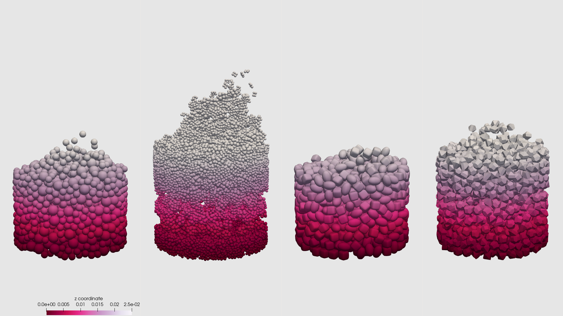
Figure 2: Resulting particle distribution with particles being colored by their z-coordinate. Further you can see more complex versions of spout beds simulations using spheres, multispheres, superquadrics and convex particles.