mesh_module servo
Purpose
Command for enabling a servo mesh wall.
Syntax
mesh_module servo keyword value
Keywords:
Keywords |
Description |
|---|---|
id |
obligatory, user-defined name for the mesh module |
obligatory position vector of the center of mass
units: [length]
|
|
obligatory, maximum velocity magnitude for servo wall
units: [length/time]
|
|
obligatory, target value for the controller (force or torque, depending on ctrlPV)
units: [mass*length/time^2] or [mass*length^2/time^2]
|
|
force or torque, selects control process modedefault:
force |
|
vector direction to apply the controlled mesh motion
default: (0, 0, -1)
|
|
auto or pid, selects controller algorithmdefault:
pid |
|
constant for the alternative controller approach (obligatory if |
|
proportional constant for PID controller (
mode = pid)default: 1e-2
|
|
integral constant for PID controller (
mode = pid)default: 0.0
|
|
differential constant for PID controller (
mode = pid)default: 0.0
|
Examples
mesh_module servo id my_servo center_of_mass (0., 0., 0.) maximum_velocity 1.0 &
  target_val 10 ctrlPV force axis (0., 0., 1.) kp 5.
mesh module servo id my_servo center_of_mass (0., 0., 0.) ctrlPV torque &
  axis (0., 0., 1.) target_val 10 maximum_velocity 1. ratio 0.01 mode auto
Description
This mesh module assumes the mesh being a servo wall that compacts a particle
packing until either a total force (for ctrlPV = force) or a total torque (for
ctrlPV = torque) is acting on the mesh. The target value is defined via the
keyword target_val. The servo can act in the direction specified by the vector
following the axis keyword. Note, that this vector is always normalized; i.e.,
only its direction is relevant. If axis is unset, it is assumed to be (0, 0,
-1).
A negative value for target_val leads to a wall motion towards negative axis-direction and vice
versa. The user has to specify the center of mass (via the keyword center_of_mass) and the maximum
velocity allowed for the servo wall (via the keyword maximum_velocity). Note that maximum_velocity
must be positive and smaller than  , where
  is the skin factor
and
is the skin factor
and  is the time-step. For cases where the control variable is the
force (
is the time-step. For cases where the control variable is the
force (ctrlPV = force), the maximum velocity is the linear velocity of the wall. For cases
where torque is the control value (ctrlPV = torque), maximum_velocity corresponds to the maximum tangential
velocity.
Two different controllers modes available, a proportional-integral-derivative (PID) controller and an alternative
controller (auto). The PID constroller (mode = pid) is controlled by three constants kp, ki, kd as follows:
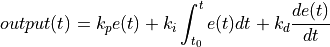
where  is the current deviation of the control process value to the target value. The
controller also includes an “anti-wind-up scheme” which prohibits accumulation of erroneous controller
output caused by the integral part due to unavoidable long-lasting deviations.
is the current deviation of the control process value to the target value. The
controller also includes an “anti-wind-up scheme” which prohibits accumulation of erroneous controller
output caused by the integral part due to unavoidable long-lasting deviations.
By using the keyword mode = auto an alternative controller approach is applied. It is a pure proportional
controller with gain scheduling. In the absence of neighbour particles the servo wall may move with maximum
velocity (defined by maximum_velocity). Otherwise, the maximum wall velocity is defined by 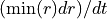 ,
where
,
where  denotes the minimum particle radius and
  is the coefficient defined by the
keyword
is the coefficient defined by the
keyword ratio. Approaching target_val the maximum velocity decreases to 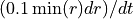 .
.
Additional information
This mesh module stores a global vector with three components for access by various output commands. The three components output the current position of the center of mass of the geometry. For easier use the property values can also be accessed via the property name: for example, id_myMesh.xcm will return the x-position of the center of mass. See the table below for a complete overview of the available properties and how to access them.
Mesh module property |
property name (dot access) |
probable array position |
center of mass |
xcm, ycm, zcm |
10-12 |
Furthermore, this mesh module writes the state of the servo wall to binary restart files so that a simulation can continue correctly.
Details about the usage of the modify command
This mesh module supports modify_command with option servo/integrate = ‘start’ or ‘stop’
to start or stop the servo wall integration in-between two runs, with option servo/target_val = val to change the
target value in-between two runs, with option servo/vel_max = val to change the target value in-between two runs,
and with option servo/ctrlParam = kp ki kd to change the controller params in-between two runs (old_style must be
set to ‘yes’ in all these cases).
Restrictions
When using this mesh module, along with scaling or rotate the body, all the servo_keyword/value pairs have to represent the state after scaling/rotation. Mesh elements may not be deleted in case due to leaving the simulation box for a fixed boundary. In this case, an error is generated. See boundary_conditions command for details. This mesh module can not be used in conjunction with another commands that manipulates mesh geometry, such as a mesh_module motion or the mesh_module 6dof.