mesh_module motion
Purpose
Command for enabling mesh motion.
Note
This command is supported by Aspherix GPU.Syntax
mesh_module motion id module-ID style keyword value
Keywords:
Keywords |
Description |
|---|---|
id |
obligatory, user-defined name for the mesh module |
meshes |
obligatory, list of IDs of the meshes to which the command is applied |
Available styles: linear, wiggle, viblin, excenter, rotate, riggle, vibrot, coin, file, follow/6dof
Style specific syntax
Every motion style has its own keywords.
Style |
Keyword |
Description |
|---|---|---|
velocity |
obligatory velocity vector
units: [length/time]
|
|
axis |
obligatory vector defining the direction of the rotation axis |
|
origin |
obligatory, origin of the axis
units: [length]
|
|
period |
period of rotation; mutually exclusive with omega
units: [time]
|
|
omega |
angular velocity of rotation; mutually exclusive with period
units: [radian/time]
|
|
filename |
no keyword, just use the name of file containing the movement data |
|
time_offset |
optional, offset of movement
default: 0; units: [time]
|
|
center_of_rotation |
optional, center of rotation
default: (0,0,0); units: [length]
|
|
use_local_frame_displacement |
yes or no; indicates whether local or global referenceframe is used for displacement vector
default:
no |
|
use_local_frame_rotation |
yes or no; indicates whether local or global referenceframe is used for rotation axis
default:
no |
|
initial_shift |
yes or no; shift mesh to position indicated by time_offsetdefault:
no |
|
amplitude |
obligatory, amplitude vector
units: [length]
|
|
period |
obligatory, period of oscillation
units: [time]
|
|
axis |
obligatory vector defining the direction of the rotation axis |
|
origin |
obligatory, origin of the axis
units: [length]
|
|
period |
obligatory period of rotation
units: [time]
|
|
amplitude |
amplitude of riggle movement
units: [degree]
|
|
axis |
obligatory vector defining the direction of the rotation axis |
|
origin |
obligatory, origin of the axis
units: [length]
|
|
tilting_axis |
vector defining the direction of the tilting axis |
|
period |
obligatory period of rotation
units: [time]
|
|
angle |
obligatory, tilting angle
units: [degrees]
|
|
axis |
obligatory, vector defining the direction of translation |
|
order |
obligatory, order of trigonometric series n (from 1 to 30)
range: [1,30]
|
|
amplitude |
obligatory, list of n amplitudes {A1, …, An}
units: [length]
|
|
phase |
obligatory, list of n phases {p1, …,pn}
units: [radian]
|
|
period |
obligatory, list of n periods {T1, …, Tn}
units: [time]
|
|
axis |
obligatory vector defining the direction of the rotation axis |
|
origin |
obligatory, origin of the axis
units: [length]
|
|
order |
obligatory, order of trigonometric series (from 1 to 30)
range: [1,30]
|
|
amplitude |
obligatory, list of n amplitudes {C1, …, Cn}
units: [radian]
|
|
phase |
obligatory, list of n phases {p1, …, pn}
units: [radian]
|
|
period |
obligatory, list of n periods {T1, …, Tn}
units: [time]
|
|
axis |
obligatory, vector defining the direction of the axis around which the
rigid body translates on a circular path
|
|
origin |
obligatory, origin of the axis
units: [length]
|
|
start_point |
obligatory, start point of the translational motion
units: [length]
|
|
period |
obligatory, time to complete a revolution around the axis
units: [time]
|
|
follow/6dof |
restricted feature |
Please check mesh_module follow/6dof.
Feature might not be available in your installation.
|
Examples
mesh_module motion id my_motion linear velocity (5., 5., 0.)
mesh_module motion id my_motion linear velocity (5., 5., 0.) meshes {myMeshId1, myMeshID2}
mesh_module motion id my_motion linear velocity (v_vx, v_vy, v_vz)
mesh_module motion id my_motion wiggle amplitude (-0.1, 0., 0.) period 0.02
mesh_module motion id my_motion viblin axis (0., 0., 1) order 5 amplitude {0.4, 0.1, 0.3, 0.1, 0.1} phase {1.3, 2., 0.4, 0.1, 0.} period {0.02, 0.07, 0.035, 0.023, 0.0175}
mesh_module motion id my_motion excenter origin (0., 0., 0.) start_point (1., 0., 0.) axis (0., 0., 1.0) period 1.5
mesh_module motion id my_motion rotate origin (0., 0., 0.) axis (0., 0., 1.) period 0.05
mesh_module motion id my_motion rotate origin (1., 0., 0.) axis (0., 1., 0.) omega v_omega
mesh_module motion id my_motion rotate origin (1., 0., 0.) axis (0., 1., 0.) period v_period
mesh_module motion id my_motion riggle origin (0., 0., 0.) axis (1. 0. 0.) period 0.01 amplitude 0.1
mesh_module motion id my_motion vibrot origin (0., 0., 0.) axis (0., 0., 1.) order 2 amplitude {0.4, 0.1}  phase {1.3, 0} period {0.02, 0.04}
mesh_module motion id my_motion coin origin (0., 0., 0.) axis (0., 0., 1.) tilting_axis (0., 1., 0.) period 1.5 angle 15.0
mesh_module motion id my_motion file move.csv time_offset 0.1 center_of_rotation (1., 0., 0.)
Description
This module allows to update the position and velocity of a mesh. Like other
modules, motion can be loaded by a mesh command to affect the
mesh defined there, or it can point directly to defined meshes
via the optional keyword meshes. If this module is not loaded by any command
or it does not specify any meshes, it remains inactive.
linear
The linear style moves the mesh elements at the specified velocity, so that their
position  as a function of time is
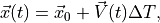
where 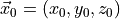 is the mesh element position at the
time when the module is activated,
is the mesh element position at the
time when the module is activated, 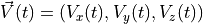 is the
specified velocity vector, and
is the
specified velocity vector, and  is the time elapsed since the
module was activated.
is the time elapsed since the
module was activated.
rotate
The rotate style imposes on the mesh a rotation around the axis defined by the keywords
axis and origin. The axis keyword specifies the axis direction, while the origin
keyword defines its origin location. The period of rotation or the angular velocity
have to be specified by the user via the keywords period and omega, respectively. The
direction of rotation around the axis is consistent with the right-hand rule: if your right-hand’s
thumb points along the axis direction, then your fingers wrap around the axis in the direction
of rotation.
file
The file style updates the position and velocity of the mesh elements based on
movement data read from a file. The file, which name is specified by the keyword
file, should have the following format
# All lines starting with a '#' are considered as comments and are ignored
# tend, dx, dy, dz, dPhi, axisX, axisY, axisZ
1.0, 2.0, 0.0, 0.0,  0.0, 0.0, 0.0, 0.0
2.0, 0.0, 0.0, 0.0, 90.0, 0.0, 0.0, 1.0
The file needs to have exactly 8 columns. The first column (tend) contains the end time of the movement of the current line. Columns 2-4 (dx, dy, dz) contain the linear movement in the specified time interval. Column 5 (dPhi) contains the rotation angle (in degrees) and columns 6-8 (axisX, axisY, axisZ) the corresponding rotation axis.
In the above example a mesh will move linearly for time  by (2, 0, 0) and it will not rotate during this time. During time
  , the mesh will not move linearly, instead it will be rotated around
the z-axis (axisX, axisY, axisZ) by 90 degrees (dPhi). It should be noted that
the center of rotation is integrated as well. In this case, should it start
with (0, 0, 0) at time 0, then at time t = 1 the center of rotation will be
located at (2, 0, 0). After reaching the end time specified in the last line
the movement will start again from the beginning, creating a “periodic”
movement.
, the mesh will not move linearly, instead it will be rotated around
the z-axis (axisX, axisY, axisZ) by 90 degrees (dPhi). It should be noted that
the center of rotation is integrated as well. In this case, should it start
with (0, 0, 0) at time 0, then at time t = 1 the center of rotation will be
located at (2, 0, 0). After reaching the end time specified in the last line
the movement will start again from the beginning, creating a “periodic”
movement.
If the time_offset keyword is used to specify a certain offset the mesh will
be moved during initialization to reach the position it will have at that offset.
During the simulation the movement will then continue. If you wish to not shift
the mesh set initial_shift no in your input script. In this case the mesh
will start its movement from the current position and will continue with the
movement at the time specified by time_offset.
Taking again the above example with a time_offset of 1.0, the mesh would be
moved initially by (2, 0, 0) and from time the mesh would
be rotated.
In order to specify a different initial center of rotation the
center_of_rotation keyword can be used. This allows to specify a point that is
different from the origin. Note, this point will also be moved if a time_offset
is used.
In general all vectors are with respect to the global coordinate system. In case
use_local_frame_displacement is set the displacement vector will be with
respect to the local reference frame, which rotates with the object. This local
frame of reference is equal to the global one initially. Note that using a
time offset will move the local reference frame during the initial positioning.
The use_local_frame_rotation option is identical to the one for the
displacement, except that it applies the coordinate transformation to the
rotation axis.
If time_offset is set, the motion will start from the specified time_offset
as absolute time value. Note, this will move the mesh from its initial position
to the position it would have at the time specified by time_offset
instantaneously.
wiggle
The wiggle style moves the mesh elements in an oscillatory fashion, so that
their position as a function of time is
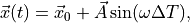
where is the mesh element position at the
time when the module is activated,  is the
amplitude vector specified by the
is the
amplitude vector specified by the amplitude keyword,  where
where T is specified by the period keyword, and is the time
elapsed since the module was activated.
riggle
The riggle style imposes one the mesh an oscillatory rotation around the axis defined
by the keywords axis and origin (the axis keyword specifies the axis direction,
while the origin keyword defines the location). The period and amplitude of the oscillation
are specified by the period and amplitude keywords in time unit and degrees, respectively.
coin
The coin style describes the motion of coin wobbling. The coin is rolling on its
perimeter; thus a point on the perimeter of the coin performs only linear up and down
motion, but no rotation around the axis defined by the axis and origin keywords.
The motion can be described by a tilting axis that is rotating around the center axis.
The tilting axis defined by the tilting_axis keyword points into the direction of the
initial tilting, the angle keyword defines the tilting angle and period the time of
one full round.
viblin
The viblin style moves the mesh elements in an oscillatory fashion using a
generic n-order vibration function, so that their position
as a function of time is
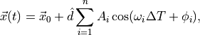
where is the mesh element position at the
time when the module is activated, n represents the order of the trigonometric
series,  are the amplitudes specified by the
 amplitude
keyword,  is the unit vector along which the oscillating translation
occurs (it is equal to the normalized vector specified by the
is the unit vector along which the oscillating translation
occurs (it is equal to the normalized vector specified by the axis keyword).
The angular velocities are  , where
 are specified by the
 period keyword, is
the time elapsed since the module was activated, and  are
specified by the
are
specified by the phase keyword.
vibrot
The vibrot style imposes an oscillatory rotation around the axis defined by the keywords
axis and origin (the axis keyword specifies the axis direction, while the origin
keyword defines the location). The rotation angle is a function of time and equal to
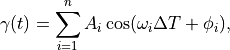
where n represents the order of the trigonometric series, are the
amplitudes specified by the amplitude keyword,
are the angular velocities, where are specified by the period keyword,
is the time elapsed since the module was activated, and
are specified by the phase keyword. Both the amplitudes and the phases are specified in radians.
excenter
The excenter style imposes on the mesh a pure translational motion along a circular path.
The keywords axis and origin define univocally the axis around which the mesh revolves
(the axis keyword specifies the axis direction, while the origin keyword defines the
location). The motion starts from the point defined by the start_point keywords. Finally,
the period keywords defines the time required for one full rotation.
Note
If a dangerous neighbor list build is detected, this may be due to the fact that the geometry has moved too close to a region where particle insertion is taking place so that initial interpenetration happens when the particles are inserted.
Superposition of multiple motions
It is possible to superpose multiple motions by applying multiple mesh_module motion
onto the same mesh. In this case, the reference frame for the second command is solidal
with the mesh moved by the first command.
Consider the following example. A mesh should rotate around a central axis and additionally revolve around its center of mass. The first move command should be the rotation around the central axis, the second move command the revolution around the center of mass of the mesh.
Because of this, the order of these commands is important. A mesh_move rotate that
comes before a mesh_move linear would have a fixed center of rotation, whereas in the
opposite case the center of rotation would move linearly with the object.
Additional information
This command writes the original coordinates of moving elements to binary restart files, so that the motion can be continuous in a restarted simulation. See the read_restart command for info on how to re-specify a command in an input script that reads a restart file, so that the operation of the command continues in an uninterrupted fashion.
None of the modify_command options are relevant to this command.
Restrictions
If multiple mesh_module motion are superposed onto one mesh, they have to be deleted in
reverse order of their creation.