mesh_module heattransfer
Purpose
Command for enabling heat transfer between mesh elements, particles and fluid.
Syntax
mesh_module heattransfer keyword value
Keywords:
Keyword |
Description |
|---|---|
id |
obligatory, user-defined name for the mesh module |
available options:
legacy, coefficient (recommended), constant, flux or powermode dependent keywords can be found below
default:
legacy |
|
obligatory except for restart; initial temperature of all wall elements in temperature units
units: [temperature]
|
|
yes or no, include / do not include the mesh internal heat transferyes requires non-zero wall_thickness / thickness_layers_wall (see keywords below)default:
yes |
|
density of material that the wall is made of (optional, derived from mesh material if not provided)
units: [mass/length^3]
|
|
available options:
yes or nodefault:
no |
|
available options:
yes or nodefault:
no |
|
available options:
yes or nodefault:
no |
Keywords for heat_transfer_mode coefficient
Keyword |
Description |
|---|---|
mandatory; wall-fluid heat transfer coefficient
units: [power/(length^2*temperature)]
|
|
mandatory; temperature of exterior (far field) fluid
units: [temperature]
|
|
thickness of each mesh element
units: [length]
|
|
list of thickness of layers {thickness_layer_1, thickness_layer_2, …}
units: [length]
|
|
list of thermal conductivities kappa of layers {kappa_layer_1, kappa_layer_2, …}
only usable in combination with
thickness_layers_wallunits: [power/(length*temperature)]
|
|
ID of region to select the mesh elements where the exterior temperature is applied |
wall_thickness and thickness_layers_wall are mutually exclusive, one of them is mandatory.Keywords for heat_transfer_mode constant
No keywords, the mesh will remain at the initial temperature.
Keywords for heat_transfer_mode flux
Keyword |
Description |
|---|---|
heat flux density
units: [power/length^2]
|
|
thickness of each mesh element; mandatory if
include_tangential_heatflux is yes (default)units: [length]
|
Keywords for heat_transfer_mode power
Keyword |
Description |
|---|---|
heat flux
units: [power]
|
|
wall_thickness, mandatory if |
thickness of each mesh element
units: [length]
|
ID of region to select the mesh elements where the exterior temperature is applied |
Keywords for heat_transfer_mode legacy
Keyword |
Description |
|---|---|
mandatory; thickness of each mesh element
units: [length]
|
|
wall-fluid heat transfer coefficient
units: [power/(length^2*temperature)]; default: 0
|
|
temperature of fluid surrounding each mesh element
units: [temperature]; default: 0
|
|
heat flux density
units: [power/length^2]
|
Keywords for enable_radiation yes
Keyword |
Description |
|---|---|
filename of the view factors file
units: [time]; default: 1e-2
|
|
filename of the view factors file
default: same file as in enable_heat_transfer
|
Associated material properties
Material properties
thermalConductivity( ): thermal conductivity of a material [
 ]
]thermalCapacity( ): thermal (specific) capacity of a material [
 ]
]youngsModulusOriginal( ): original Young’s modulus of each material [
 ] (required if
 area_correction yesis used in the wall_contact_model command)
Material interaction properties
ht_modification( ): modifier for contact area calculation [
 ] (required if
 modified_area_correction yesis used in the wall_contact_model command)
Examples
mesh_module heattransfer id my_heattransfer wall_density 500. wall_thickness 0.01 initial_temperature 300. &
   temperature_fluid 200. heat_transfer_coefficient_fluid 0.01
mesh_module heattransfer id my_heattransfer heat_transfer_mode coefficient initial_temperature 300 &
  htc_exterior_fluid 0.01 temperature_exterior_fluid 400 thickness_layers_wall {0.01,0.02} &
  kappa_wall_layers {0.5,1.0} include_tangential_heatflux yes
mesh_module heattransfer id my_heattransfer heat_transfer_mode constant initial_temperature 300
mesh_module heattransfer id my_heattransfer heat_transfer_mode flux flux_value 10 initial_temperature 300 &
  wall_thickness 0 include_tangential_heatflux no
mesh_module heattransfer id my_heattransfer heat_transfer_mode power power_value 1 initial_temperature 300 &
  wall_thickness 0.01
mesh_module heattransfer id my_heattransfer heat_transfer_mode coefficient &
  initial_temperature 300 htc_exterior_fluid 0.01 temperature_exterior_fluid 400 thickness_layers_wall {0.01,0.02} &
  kappa_wall_layers {0.5,1.0} include_tangential_heatflux yes
mesh_module heattransfer id my_heattransfer heat_transfer_mode coefficient wall_thickness 0.18 &
  temperature_exterior_fluid function(temp.csv,x) htc_exterior_fluid 0.01 initial_temperature 500 id mm1 &
  active_region my_active_region
mesh_module heattransfer id my_heattransfer heat_transfer_mode constant initial_temperature 300 enable_radiation yes
Description
This mesh module can solve for three different mechanisms of heat transfer associated to the mesh:
heat transfer between particles and mesh elements
heat transfer between mesh elements and the exterior fluid
heat transfer between mesh elements
The heat transfer between particles and mesh is identical to the implementation in the enable_heat_transfer command. The thermal capacity and conductivity values for particle and wall material are defined via the material_properties commands.
Warning
Although heat_transfer_mode legacy is the default setting (for backward
compatibility), any other heat transfer modes is preferred.
With heat_transfer_mode coefficient the heat transfer between the mesh
elements and an exterior fluid is included. It is assumed that the exterior
fluid is located at one side of the mesh, is at rest and has constant (in time)
temperature; hence, only conductive heat transfer is considered. Note that the
temperature_exterior_fluid can be set to a scalar value, or provided via a csv
data file (to make it location dependent). In the latter case, the following
formatting has to be used in the input file:
temperature_exterior_fluid function(my_temp_data.csv,spatial_direction)
Here ‘my_temp_data.csv’ is a file with two columns: the first column contains a spatial
position (along the ‘spatial_direction’ axis, which must be set to ‘x’, ‘y’, or ‘z’) and
the second column the exterior temperature at the position. The exterior temperature of
mesh elements is derived (interpolated based on the center point of the mesh element)
from the provided values at initialization via a precomputed lookup table. In order to
apply the exterior temperature condition only to certain mesh elements, the active_region
can be set. This will ensure only mesh elements with their center point within the
active region will apply the temperature boundary condition. Note that the active region
does not affect the (tangential) heat conduction within a mesh, which is enabled by default
via the include_tangential_heatflux option. If no active region is set, the temperature
boundary condition will be applied to all mesh elements.
From the heat transfer coefficient of the exterior fluid and the thickness and thermal conductivity (kappa) values of the wall layers (defined by thickness_layers_wall and kappa_layers_wall), a total heat transfer coefficient is determined according to:
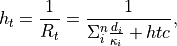
where  is the total thermal resistance,
  and
and
 are the thickness and thermal conductivity of wall
layer
are the thickness and thermal conductivity of wall
layer  (there are in total
  layers), and
  is the heat transfer coefficient of the exterior fluid.
For heat_transfer_mode legacy the total heat transfer coefficient is
determined as:

where  is the wall-fluid heat transfer coefficient (note that
its dimensions are different from , so a more proper naming would
be thermal conductivity) and
is the wall-fluid heat transfer coefficient (note that
its dimensions are different from , so a more proper naming would
be thermal conductivity) and  is the wall thickness.
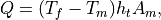
where  is the heat flux,
  is the (exterior) fluid
temperature,
is the (exterior) fluid
temperature,  is the temperature of the mesh element,
  is the total heat transfer coefficient, and
  is the area of the mesh element.
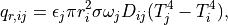
For heat transfer between mesh elements, a similar formula is used:
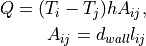
where  is the length of the edge that is shared between
mesh elements i and j, and is the wall thickness,
that has to be specified by the user. The thermal conductivity is
taken from the material_properties
commands defining the thermal conductivity for the wall material
(also for a layered wall), see enable_heat_transfer.
is the length of the edge that is shared between
mesh elements i and j, and is the wall thickness,
that has to be specified by the user. The thermal conductivity is
taken from the material_properties
commands defining the thermal conductivity for the wall material
(also for a layered wall), see enable_heat_transfer.
The mesh can be used as a heat source/sink with a defined heat flux
density  (which is the
 flux_value for heat_transfer_mode flux).
A heat flux of
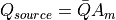
with the mesh element area is then added to each triangle.
For heat_transfer_mode power the power_value is directly used as
 , without being effected by the mesh element area.
For the temperature update of each mesh element initial_temperature
is used as initial condition, which can be set to a scalar value or provided via a csv
data file (by a function to make it location dependent, see the description for the
temperature_exterior_fluid).
The mass of each mesh element is calculated from its area, the value for wall_thickness and the
density, which is taken from the material_properties commands (also for a layered wall), but can
be overridden via the wall_density keyword for backwards compatibility.
Please note that the initial_temperature keyword is obligatory only if the simulation
is started from scratch (in that case it replaces the temperature keyword of the mesh
command). For restarted simulations it is an optional keyword, which is used to (re)set
the temperature in each mesh element. If the heat transfer mesh module was not enabled when
generating the restart file and the initial_temperature keyword is omitted, the
temperature in each mesh element will be set to zero. If the initial_temperature is used
in combination with a simulation restart, a warning will be written to the screen/output file.
With output_detailed_heatflux it is possible to include detailed heat flux information (for
each component contributing to the heat flux) to the mesh output as done by output_settings.
Additionally, this keyword also creates two additional per-particle properties
heatFluxWallConduction and heatFluxWallRadiation which output the
instanteaneous heat flux a particle experiences due to the heat flux coming
from a mesh for both conduction and radiation, respectively.
Warning
Mesh module heattransfer implements a very simplistic way of computing heat transfer on meshes, and it might lead to mesh-dependent results, especially in the case of (a) skewed triangles and (b) very fine meshes. When in doubt about the results, try using a mesh with larger, (preferrably) equilateral triangles.
Warning
When using this module and periodic boundary conditions the mesh needs to fulfill the following properties: (i) a triangle is not allowed to be in contact with itself through periodic boundaries, (ii) if two triangles are in contact inside the domain, they are not allowed to be in contact through periodic boundaries. Note that these restrictions are not validated by Aspherix(R) and must be ensured by the user.
Warning
It is not possible to have heat transfer between separate meshes. Only particle-particle, particle-wall and wall internal heat transfer is possible. Note also that mesh elements only exchange heat with each other if the elements share an edge. Therefore, a cylinder with baffles will only exchange heat between the cylinder and baffles if they are part of the same mesh (stl) and if the baffles share an edge with one of the elements of the cylinder.
In case enable_radiation is set to yes a radiation model based on local
void fractions and particle-wall distance is employed using view factors read
from a file.
Radiation model
The model that was implemented is based on the work of Johnson et al. [2].
It defines the heat transferred from a wall element  to a particle
as
to a particle
as
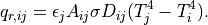
For a description of the involved quantities see the
particle-particle heat transfer
including the description of the view_factors_file. As the view factor
depends on the volume which can be reduced by the presence of a wall we use
the integral theorem to calculate it, i.e.
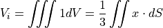
This surface integral can then be approximated via a ray summation, i.e. 128 equally spaced rays are cast from the center to the surface of the influence sphere and the volume is then approximated via
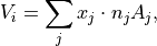
which, if the ray hits no triangle, reduces to

where  is the number of rays and to
where  is the intersection point of ray with triangle and
 is the normal of the triangle.
The update of this local influence volume of each particle is done every
radiation_update_timestep time units. The void fraction of a particle
close to a wall is then computed using the sum of the volume of all
particles in its sphere of influence divided by  .
.
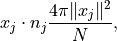
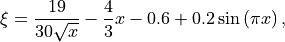
The lookup table present in the view factors file is for a plane which has a certain distance to the particle. Thus, if the wall is discretized using multiple triangles not every triangle should contribute the full view factor. Instead there must be a weight which is based on the percentage of the triangle that covers this plane. We decided that this weight function should be
where the integral over the full plane is
with  ,
,  the radius of the sphere of influence and
  the normal distance to the triangle. The weight can then be approximated as the sum over all rays using
where  is an empirical correction factor that corrects a systematic approximation error via
with  . The number of estimated ray hits of a plane with a certain distance is given as
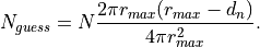
Thus, the final equation reads
where  depends on the volume fraction, which is corrected by the approximated
  .
.
External heat flux
In case add_external_heatflux is set to yes an external heat flux is
imposed on the mesh
Details on add_external_heatflux
This keyword allows using an external application to impose an additional heat flux on a mesh.
To see how the external application can interact with Aspherix see the
enable heat_transfer command. To
allow using this keyword the mesh_properties
keyword in the output_settings command must
contain the heatFluxExternal value. The per-triangle heat flux written
by the external application is then read in by Aspherix and applied to the
mesh.
Additional information
This mesh module writes information to binary restart files to be able to continue correctly after restart. None of the modify_command options are relevant to this module.
This module stores per-mesh-element properties (“Temp”: temperature and “heatFlux”:
aggregated heat flux) which can be accessed via output_settings.
Moreover, it stores the average mesh temperature accessible via the entry avg_temp for the mesh.
If the exterior temperature is set via a function, the TempAmbient per-mesh-element property is
available for output as well. If an active_region is used, also the active per-mesh-element
property is available. If add_external_heatflux yes is used, the heatFluxExternal per-mesh-element
property will be available. If output_detailed_heatflux is used, one or more of the following
per-mesh-element properties (depending on the settings of this command) are available for output as well:
heatFluxExteriorConduction, heatFluxParticleConduction, heatFluxParticleRadiation,
heatFluxSource, heatFluxWallConduction.
Restrictions
This module specification must be followed by the enable_heat_transfer.