region command
Purpose
Command for defining a region in a simulation.
Note
This command is supported by Aspherix GPU.Note
The following region types are supported by Aspherix GPU: block, cylinder, sphere;
Syntax
region keyword value
Keywords |
Description |
|---|---|
obligatory, user-assigned name for the region |
|
General optional keywords
Keywords |
Description |
|---|---|
available options:
in, out; region is inside / outside specified geometrydefault:
in |
|
available options:
lattice, box; region is defined in lattice / simulation box unitsdefault:
box |
|
vector with displacement in x, y, and z direction, arguments can be values or equal style variables
if the region displaces over time
default: (0, 0, 0); range: (-∞,∞) per component; units: [length]
|
|
angle value point origin_vector axis axis_vector, angle: constant value or equalstyle variable for the rotation angle of the region (in radians), point: vector of origin
of rotation axis (non-mandatory), axis: axis of rotation
units: [radian] (value), [length] (origin_vector), [-] (axis_vector)
|
|
seed |
seed for placing random points in the region
default: 3012211; units: [-]
|
volume_limit |
minimal volume of the region used for sanity checks
default: 1e-10; units: [length^3]
|
Style specific keywords
The list below provides the user with the specific keyword/argument pairs for
the different region styles.
Basic regions:
Composite regions:
Examples
region id my_block style block low (-3, INF, EDGE) high (5., 10., INF)
region id hs style halfspace point (0, 0, 5) normal (0, 0, 1)
region id my_cone style cone center_bottom (0, 1, 0) center_top (0, 2, 0) radius_bottom 1 radius_top 0
region id my_sphere style sphere center (0, 2, 3) radius 3.14 side out
region id my_cylinder style cylinder center_bottom (0, 1, 0) center_top (0, EDGE, 0) radius 2 units box
region id my_prism style prism low (0, 0, 0) high (10, 1, 2) tilt_y_to_x 3
region id my_mesh style mesh/vtk file volmeshfile.vtk
region id my_sphere2 style sphere center (0.0, 0.0, 0.0) radius 5 side out translate (v_left, 1., 0.)
region id my_wedge style wedge center_bottom (0, 0, 0) center_top (0, 0, 1) radius 0.5 edge (1, 0, 0) opening_angle 50
region id outside style union regions {side1, side2, side3, side4} side out
region id int style intersect regions {my_block, my_cone}
region id sub style subtract base_region domain operand_regions {side1}
region id my_region style delete
variable angle equal 0.785*time
region id insreg style cylinder center_bottom (-0.031,0.0,-0.1) center_top (-0.031,0,0.1) radius 0.06 &
                 translate (0.0001,0.0001,0.0001) rotate angle v_angle point (0,0,0) axis (0,0,1)
Description
This command defines a geometric region of space. Various other commands use regions, e.g., for particle insertion, particle deletion, the application of forces or the evaluation of properties.
The region boundaries are considered to be a part of the region, i.e., if a particle′s
coordinates are exactly at the region boundary it is considered as part of the region if
the region is defined with option side in (default) and not part of the region with
option side out.
The side keyword determines whether the region is considered to be inside or outside
of the specified geometry. Using this keyword in conjunction with union, intersect
or subtract, complex geometries can be built up.
The units keyword determines the meaning of the distance units used to define the region.
It affects all quantites that involve distance metrics such as rotation points or velocities.
The standard option box selects the standard distance units as defined by the units
command (default: si). For using style lattice, a lattice command
must be used to define the lattice spacings beforehand.
Normally, regions in Aspherix® are static, their geometric extent does not change with
time. If the translate or rotate keyword is used with equal style variables,
regions can become dynamic and its location / orientation can change with time.
These keywords cannot be used with a union or intersect style region, but they
can be applied to all involved sub-regions instead.
The translate keyword allows one or more equal-style variables to
be used to specify the x,y,z displacement of the region, also as a function of time.
A variable is specified as v_name, where name is the variable name. Any of the three
variables can be specified as NULL, in which case no displacement is calculated in that
dimension. Alternatively, each variable can also be set as a constant value.
Example for displacement of region in x-direction at constant velocity:
variable dx equal ramp(0,10)
region 2 sphere center (10.0, 10.0, 0.0) radius 5 translate (v_dx, 0., 0.)
Note that the initial displacement is 0.0, though that is not required.
Example for region wiggling in y-direction:
variable dy equal swiggle(0,5,100)
variable dysame equal 5*sin(2*PI*elaplong*dt/100)
region 2 sphere center (10.0, 10.0, 0.0) radius 5 translate (NULL, v_dy, NULL)
The rotate keyword rotates the region around a rotation axis R = (Rx,Ry,Rz) that goes
through a point P = (Px,Py,Pz). The rotation angle is calculated, presumably as a function
of time, by a variable specified as v_theta, where theta is the variable name (angle in radians).
The direction of rotation for the region around the rotation axis is consistent with the
right-hand rule.
The translate and rotate keywords can be used in combination. In this case,
the displacement specified by the translate keyword is applied to the P
point of the rotate keyword.
The lo/hi values for block or cone or cylinder or prism styles can be specified as EDGE
or INF. EDGE means they extend all the way to the global simulation box boundary. Note that this is the
current box boundary; if the box changes size during a simulation, the region is not adapted. INF means
a large negative or positive number (1.0e20), so it encompasses the simulation box even if it changes
size. If a region is defined before the simulation box has been created (via simulation_domain
or read_data or read_restart commands), then an EDGE or INF
parameter cannot be used. For a prism region, a non-zero tilt factor in any pair of dimensions cannot
be used if both the lo/hi values in either of those dimensions are INF. E.g. if the tilt_y_to_x is
non-zero, then xlo and xhi cannot both be INF, nor can ylo and yhi.
Warning
Regions in Aspherix® do not get wrapped across periodic boundaries, as specified by the boundary_conditions command. For example, a spherical region that is defined so that it overlaps a periodic boundary is not treated as 2 half-spheres, one on either side of the simulation box.
Regions in Aspherix® are always 3D geometric objects, regardless of whether the dimension of a simulation is 2D or 3D. Thus when using regions in a 2D simulation, you should be careful to define the region so that its intersection with the 2D x-y plane of the simulation has the 2d geometric extent you want.
For style cone, an axis-aligned cone is defined which is like a cylinder except that two
different radii (one at each end) can be defined. Either of the radii (but not both) can be 0.0.
For style halfspace, a plane is defined which contains the point (px,py,pz) and has a normal
vector (nx,ny,nz). The normal vector does not have to be of unit length. side in marks the
half-space in the direction of the normal vector.
Region style prism defines a parallelepiped. Two points are used to set up the untilted box
and tilt factors are used to for the transformation of the box to the desired parallelepiped.
A prism region that will be used with the create_box command to define a triclinic simulation box must have tilt factors (xy,xz,yz) that do not skew the box more than half the distance of corresponding the parallel box length. See the HowTo for triclinic simulations of the doc pages for a geometric description of triclinic boxes, as defined by Aspherix®, and how to transform these parameters to and from other commonly used triclinic representations.
The radius value for style sphere and cylinder can be specified as an equal-style
variable. If the value is a variable, it should be specified as v_name, where
name is the variable name. In this case, the variable will be evaluated each timestep, and
its value used to determine the radius of the region.
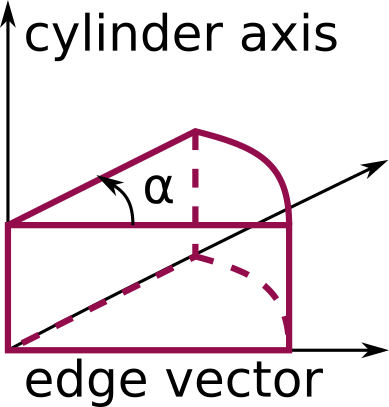
The wedge style is a cylindrical sector (cake slice). The definition of the cylinder is equal to
the definition of a cylinder style region. The edge vector defines the second axis, and
together with the cylinder axis spans one face of the wedge. Which side of the
cylinder becomes the wedge is then defined by the third axis according to the
right-hand rule. Finally, the opening_angle value defines the opening angle of
the cylindrical sector measured from the previously defined side face. This is
shown in the schematic below.
The union style creates a region consisting of the volume of all the listed
regions combined. The intersect style creates a region consisting of the
volume that is common to all the listed regions. The subtract style creates a
region consisting of the volume that is in the base_region region, but not in
the ones listed after the operand_regions keyword.
The delete style does not require an argument and is used to delete an existing
region.
Warning
The union, intersect and subtract regions
operate by invoking methods from their list of sub-regions. Thus you
cannot delete the sub-regions after defining the union,
intersection or subtract region.
Restrictions
A prism cannot be of 0.0 thickness in any dimension; use a small z thickness for 2D
simulations. For 2D simulations, the tilt_z_to_x and tilt_z_to_y parameters must be 0.0.