 Home
HometwoWaySocket
Syntax
Defined in couplingProperties dictionary.
dataExchangeModel twoWaySocket;
twoWaySocketProps
{
    verbose          switch;
    bbOffset         scalar;
    timeOut          label;
    nTries           label;
    portFilePath     "../DEM";
    hyperthreading   switch;
    triggerDEMOutput switch;
};
verbose = give verbose output (default: false)
bbOffset = enlarge the CPU bounding box by this value in every direction. Will lead to partcles being communicated to several CFD processes. (default: 0)
timeOut = wait time in seconds for start up of DEM solver and successful socket connection (default: 1)
nTries = number of tries to connect to DEM solver socket server (default: 10)
portFilePath = search path for portOffset files (default: “../DEM”)
portBase = use as base port, must be identical to value for
port_basein enable_cfd_coupling command (default:49152)hyperthreading = If
truethen DEM and CFD calculate the same time step in a concurrent manner, i.e. the processes run at the same time. This setup requires two threads per core (usecfdemSysTestorlscpucommand to check). In case only one thread per core is available you should usefalsefor optimal performance. In this setup the processes are run in a conscutive manner, i.e. the CFD runs while the DEM is idle and vice-versa. Note: this overrides the CFDEM_SOCKET_HYPERTHREADING environment variable. (default: true).triggerDEMOutput = trigger writing of DEM result files on CFD output times (default: true)
Examples
dataExchangeModel twoWaySocket;
twoWaySocketProps
{
    verbose true;
    bbOffset 1e-3;
    timeOut 10;
    nTries  12;
    portFilePath "./";
    hyperthreading on;
}
Description
The data exchange model performs the data exchange between the DEM code and the CFD code. The twoWaySocket model is a model that can exchange trivial particle properties from DEM to CFD (e.g. position, radii) and from CFD to DEM (e.g. dragforce). Data is exchanged via a standardized socket interface by sequentially writing/reading data. Both codes have to run separately and are not linked. The before mentioned standardized socket interface can also be used to exchange data between the DEM code and a completely different CFD code (e.g. based on Lattice Boltzman Method).
Each CFD process calculates its own bounding-box from its mesh and adds an
optional offset bbOffset to the boundary, enlarging the domain on each CPU .
This is used in the DEM code to determine where to send the particle data.
During start up the dataExchangeModel searches for portOffset_* files in the
portFilePath (default is ../DEM). If not successful, the model waits
timeOut seconds (default is 1 second) and it repeats the attempt to a total
of nTries (default is 10) times.
If triggerDEMOutput true (the default) is set, the CFD will trigger the DEM side
to write results whenever CFD results are written. This behavior will result in
result files from both sides at matching times.
This behavior requires the existence of a writeAsx model
and overrides settings made with the write_output_timestep in an Aspherix input script.
Note
Triggering DEM output from the CFD requires that output to be configured on the DEM side, i.e. your input script should contain an output_settings command.
Caution
Do not manually create restart files in the DEM input script, e.g. using the restart command, and trigger output from the CFD side (i.e. use the default settings) at the same time as this combination may lead to incomplete / corrupted restart files. We strongly recommend to keep the default settings.
This model also exchanges global data with the DEM side, e.g.
gravity as set on the DEM side using the enable_gravity command, see Special handling of gravity
the DEM time step as set using the simulation_timestep command
fluid viscosity and density as set on the CFD side
Communication setup with DEM
When setting up a coupled simulation the variables communicated from CFD to DEM and vice-versa must match by name and type (scalar, vector, etc.) in both directions. The communication is set automatically with the socket connection and tries to create all necessary variables on the DEM side to correspond to the setting on the CFD side. If this setup fails because variables are, for instance, not available or not created an error message listing the problematic properties is displayed. Which variables are transferred can be controlled on the DEM side using the enable_cfd_coupling command.
Hyperthreading
The CFD and DEM solvers are executed as separate programs that can be run in two different execution modes:
concurrent: Both programs run at the same time as different threads on the same core.
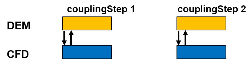
consecutive: CFD and DEM calculations steps are run after one another on the same core.
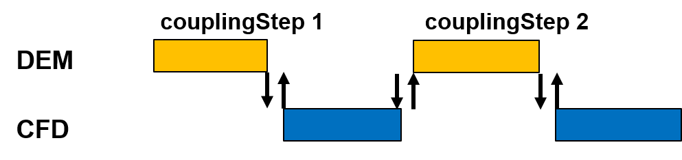
The hyperthreading switch defines which execution mode is selected and, thus,
how the scheduling of the CFD and DEM executables is handled.
The default is on, which leads to concurrent execution of the
executables. hyperthreading off will select the consecutive execution mode.
The benefit in concurrent execution is a slightly improved overall performance.
Since most CPUs support multiple threads per core, this setting is the default and,
generally, maximizes utilization of available computational resources.
However, on some CPUs only one thread is active and by default MPI will place and
bind the processes of both executables on the same cores.
In this case, both executables will hinder each other and performance will decrease.
With hyperthreading off the executables wait each others turn and
performance is optimal for this CPU type.
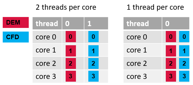
Process placement if hyperhtreading is available on the CPU (left) and if not available (right). In the latter case both processes are placed on the same cores.
Note
To find out if hyperthreading is available on your CPU type, run the
cfdemSysTest command and check the output under the “Hyperthreading” header.
On HPC resources, make sure to run cfdemSysTest on the actual computational
hardware, i.e. on the compute node and not on the login node.
In a addition to this per-case setting, the CFDEM_SOCKET_HYPERTHREADING
environment variable can be set to apply a custom default value.
Add export CFDEM_SOCKET_HYPERTHREADING=off to your bashrc to set this as
system-wide default.
Note
The runtime of the Ergun case can serve as a benchmark here to detect performance issues, e.g. due to using an inappropriate run mode. It should take a bit more than thirty seconds.
Restrictions
Note
timeOut must be given in seconds and does only accept values as full seconds.
This means that time out values smaller than one second are not allowed.
Note
This model requires the usage of an enable_cfd_coupling command on the DEM side.