Insertion of particles
Description:
This text describes how to insert one or more particles in Aspherix® simulations.
Introduction:
There are two main commands that allow the insertion of one or more particles: the basic create_particles and the more advanced insertion. The first one is able to insert one or more particles (actually particle templates, see particle_template) at prescribed positions, thereby having the option to also set the translational / angular velocity and particle orientation. This type of insertion is used in the region_mesh_vtk solver example as shown below (it can be found in examples/solver/insertion/region_mesh_vtk as well):
create_particles example (examples/solver/insertion/region_mesh_vtk)
# tet mesh region example

# define particles as spheres
particle_shape sphere

# size of simulation domain
simulation_domain low (-1, -1, -.05) high (1, 1, 1.05)

# skin size used in neighbor list
neighbor_list skin_size 2e-2

# material and its properties
materials {m1}
material_properties m1 youngsModulus 5e6 poissonsRatio 0.45 coefficientRestitution 0.9 coefficientFriction 0.05 density 500

# contact models
particle_contact_model normal hertz tangential history
wall_contact_model normal hertz tangential history

# time step
simulation_timestep 1e-5

# switch on gravity
enable_gravity

# define particles and a distribution
variable d equal 0.05
variable r equal $d/2
particle_template id pts1 material m1 radius $r

#region and insertion
region mesh mesh/vtk file data/cylinder.vtk
# define a square lattice with distance $d = 0.05
define_lattice mode sc scale $d
# create particles of template pts1 and region mesh
create_particles template pts1 mode on_lattice mesh

# intervals for output
write_to_terminal_timestep 1e-2
write_output_timestep 8e-3

# define output
output_settings file post/mesh_tet_*.vtm

# simulate 0.01s
simulate time 1e-2
create_particles template pts1 mode on_lattice mesh
This command line will create multiple particles (defined by particle_template pts1) on the lattice of the mesh region, where the lattice has a point-to-point distance of 0.05. To insert only a single particle at spatial position (0.0,0.1,0.2) with a velocity of (-1,-1,0), the current command line could be replaced by
create_particles template pts1 mode single position (0.0,0.1,0.2) velocity (-1,-1,0)
More advanced insertions can be accomplished via the insertion command. An important difference compared to the create_particles command is that the particles to insert are now defined by a particle_distribution (which in turn depends on one or more particle_templates). This allows the insertion of different particle shapes, sizes and types with a single insertion command. The insertion command has several modes, which define the way the particles are inserted. The available modes are: pack, stream, rate_in_region, spray_nozzle (all explained in more detail below), stream_regionfill, and laser.
insertion mode pack example (example/solver/insertion/insertion_and_growing_particles)
#Particle packing by insertion and successive growing of particles

# define particles as spheres
particle_shape sphere

# size of simulation domain
simulation_domain low (-0.05, -0.05, 0) high (0.05, 0.05, 0.15)

# skin size used in neighbor list
neighbor_list skin_size 2e-3

# material and its properties
materials {m1}
material_properties m1 youngsModulus 5e6 poissonsRatio 0.45 coefficientRestitution 0.3 coefficientFriction 0.5 density 2500

# contact models
particle_contact_model normal hertz tangential history
wall_contact_model normal hertz tangential history

# time step
simulation_timestep 1e-5

# wall definition
primitive_wall material m1 type plane normal_axis x offset -0.05
primitive_wall material m1 type plane normal_axis x offset  0.05
primitive_wall material m1 type plane normal_axis y offset -0.05
primitive_wall material m1 type plane normal_axis y offset  0.05
primitive_wall material m1 type plane normal_axis z offset  0
primitive_wall material m1 type plane normal_axis z offset  0.15

# define particles and a distribution
particle_template id pts1 material m1 radius 5e-3
particle_template id pts2 material m1 radius 8e-3
particle_distribution id pdd1 templates {pts1, pts2} fractions {0.3, 0.7}

#parameters for gradually growing particle diameter
variable alphastart equal 0.25
variable alphatarget equal 0.67
variable target_scale equal (${alphatarget}/${alphastart})^(1/3)
variable grow_time equal 0.5
variable growevery equal 4e-5 #4e-4

# insertion of particles
# insertion region
region id insertion_region style block low (-0.05, -0.05, 0) high (0.05, 0.05, 0.15)
# actual insertion command
insertion id insertion_pack mode pack particle_distribution pdd1 velocity constant (0, 0, 0) insert_every_time once region insertion_region target_volume_fraction ${alphastart}

# intervals for output
write_to_terminal_timestep 1e-2
write_output_timestep 3.5e-3

# computation of volume fraction
variable vol atom 4/3*r^3*PI
calculate sum quantity v_vol id pvol
variable volfract equal id_pvol/(0.1*0.1*0.15)

# simulate on time step
simulate time_steps 1

print "volume fraction after insertion: ${volfract}"

# stop insertion
disable_command id insertion_pack

# command to grow particles
grow_particles id grow grow_every_time ${growevery} target_scale_factor ${target_scale}

# define output
output_settings file post/packing_*.vtm

# simulate 0.5s
simulate time ${grow_time}

print "volume fraction after growing: ${volfract}"

disable_command id grow

# simulate 0.2s
simulate time 0.2
insertion id insertion_pack &
          mode pack &
          particle_distribution pdd1 &
          velocity constant (0, 0, 0) &
          insert_every_time once &
          region insertion_region &
          target_volume_fraction ${alphastart}
This command line will create a pack of particles (which configuration is based on the earlier defined particle distribution pdd1) with an initial velocity of zero. The particles will be inserted in a single time step (insert_every_time once) within the (earlier defined) insertion_region. The insertion will stop once the fill ratio of the region has reached the target_volume_fraction value. The most simplified pack insertion command would be the following:
insertion id insertion_pack &
          mode pack &
          particle_distribution pdd1 &
          region insertion_region
This command makes use of the automatic settings for the pack insertion: zero initial velocity, insertion in a single time step and a target volume fracion of 0.10.
insertion mode stream example (example/solver/insertion/insert_stream)
# define particles as spheres
particle_shape sphere

# size of simulation domain
simulation_domain low (-1, -1, -5) high (1, 1, 2.85)

# skin size used in neighbor list
neighbor_list skin_size 1e-2

# material and its properties
materials {m1}
material_properties m1 youngsModulus 5e6 poissonsRatio 0.45 coefficientRestitution 0.9 coefficientFriction 0.05 density 2500

# contact models
particle_contact_model normal hertz tangential history
wall_contact_model normal hertz tangential history

# time step
simulation_timestep 1e-5

# switch on gravity
enable_gravity

# define particles and a distribution
particle_template id pts1 material m1 radius 1.5e-2
particle_template id pts2 material m1 radius 2.5e-2
particle_distribution id pdd1 templates {pts1, pts2} fractions {0.3, 0.7}

# insertion of particles
# first define mesh through which particles will be streamed
mesh id insertion_mesh file meshes/face.stl scale 5e-3 solid no is_planar yes
# actual insertion command
insertion mode stream particle_distribution pdd1 target_particle_count 5000 velocity constant (0, -0.5, -2) particlerate 1000 insertion_face insertion_mesh extrude_length 0.6

# intervals for output
write_to_terminal_timestep 1e-2
write_output_timestep 8e-3

# run 1 time step
simulate time_steps 1

# define output
output_settings file post/stream_*.vtm

# simulate 0.1s
simulate time 1

write_restart post/liggghts.restart
insertion mode stream &
          particle_distribution pdd1 &
          target_particle_count 5000 &
          velocity constant (0, -0.5, -2) &
          particlerate 1000 &
          insertion_face insertion_mesh &
          extrude_length 0.6
This command line will insert a stream of particles (which configuration is based on the earlier defined particle distribution pdd1) with an initial velocity of (0,-0.5,-2). The particles will be inserted with a rate of 1000 particles per time unit (particlerate 1000) through an (earlier defined) insertion face (a stl mesh). The particles to be inserted are initialized in a volumetric region just behind the insertion face. The extrude_length defines the size of this volumetric region, and should be large enough so that the volumetric region can hold a sufficient amount of particles. A stream insertion command that prevents the need for an additional insertion face stl mesh and using as many default values as possible would be the following:
insertion mode stream &
          particle_distribution pdd1 &
          velocity constant (0, -0.5, -2) &
          insertion_shape square &
          x_axis (1,0,0) &
          length 0.3 &
          center (0,0.325,2.215)
This command sets the particlerate and target_particle_count automatically, and replaces the insertion_face by an insertion_shape. Valid insertion shapes are: circle, ellipse, square and rectangle, see the insertion shape section below for a more detailed explanation. The other keywords are there to fully constrain the shape, position and orientation of the shape (the velocity direction is used as its normal vector). Note that in order to use this insertion command instead of the original one, the interface_mesh needs to be disabled (otherwise an error will be shown it has not been used at all).
insertion mode rate_in_region example (example/solver/insertion/insert_stream)
#Simple chute wear test

# define the particle shape
particle_shape sphere

# define the computational domain
simulation_domain low (-0.5, -0.2, -0.4) high (0.1, 0.2, 0.15)

# define the particle skin factor
neighbor_list skin_size 0.002

# define the material properties
materials {m1}
material_properties m1 youngsModulus 5e6 poissonsRatio 0.45 coefficientRestitution 0.3 coefficientFriction 0.5 k_finnie 1 density 2500

# define the particle-particle contact model
particle_contact_model normal hertz tangential history

# define the DEM time-step
simulation_timestep 1e-5

# use gravity (default setting: 9.807 m/s in negative z direction)
enable_gravity

# load a mesh: the chute geometry
mesh id cad file meshes/simple_chute.stl material m1 solid yes

# define a region for the particle insertion
region id insertion_region style block low (-0.035,-0.035,0.05) high (0,0.035,0.1)

# define the particle-wall contact model
wall_contact_model normal hertz tangential history

# define two particle templates and the particle distribution
particle_template id smallParticles material m1 radius 1.5e-3
particle_template id largeParticles material m1 radius 2.5e-3
particle_distribution id pdd1 templates {smallParticles, largeParticles} fractions {0.3, 0.7}

# insert particles with a constant rate into the insertion region
insertion mode rate_in_region particle_distribution pdd1 target_particle_count 6000 massrate 0.1 insert_every_time 0.01 all_in no velocity constant (0,0,-1) region insertion_region

# define the output time intervals
write_output_timestep 0.002
write_to_terminal_timestep 0.01

# run one simulation time step
simulate time 1e-5

# output the particle and mesh data to files
output_settings file post_n/sim_*.vtm meshes {cad}

# run the simulation up to one second
simulate target_time 1
insertion mode rate_in_region &
          particle_distribution pdd1 &
          target_particle_count 6000 &
          massrate 0.1 &
          insert_every_time 0.01 &
          all_in no &
          velocity constant (0,0,-1) &
          region insertion_region
This command line will insert not more than 6000 particles (which configuration is based on the earlier defined particle distribution pdd1) with an initial velocity of (0,0,-1). The particles will be inserted with a particle mass rate of 0.1 mass unit per time unit (massrate 0.1) and new particles will be inserted every 0.01 time units (insert_every_time 0.01). The center points of particles will be inside an (earlier defined) insertion region (region insertion_region), but particles do not need to be completely within this region (all_in no). A minimal rate_in_region insertion command would be the following:
insertion mode rate_in_region &
          particle_distribution pdd1 &
          region insertion_region
Here the following defaults for the omitted keywords are used: insertion happens every 1000th time step (to replace insert_every_time), when 15% of the region volume fraction is inserted (to replace massrate). Every time unit 50% of the region volume fraction is to be inserted (to replace target_particle_count 6000). If the velocity is not provided, it will be set to zero.
insertion mode spray_nozzle command
insertion mode spray_nozzle &
          id my_spray_nozzle &
          particle_distribution sprayDist &
          target_mass 1 &
          massrate 0.1 &
          insert_every_time 1e-2 &
          velocity constant (0.1, 0, -1) &
          nozzle_shape cone &
          outer_cone_angle 90 &
          inner_cone_angle 40 &
          outer_nozzle_radius 3e-2 &
          inner_nozzle_radius 1e-2 &
          center_of_nozzle (-0.2, 0, -0.1)
This command will insert the particles as defined in the sprayDist particle_distribution with the defined target_mass, massrate and velocity. Insertion will happen every 0.01 time unit through a nozzle with a cone shape (which requires more detailed keywords to define its position and shape). See the section on nozzle shapes for more a detailed explanation.
Insertion shapes:
In total there are four different types of insertion shapes: circle, ellipse, square and rectangle. Below some example top (upper image) and side (lower image) views for different shapes and orientations:
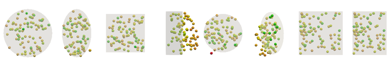
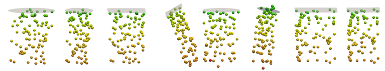
insertion_shape circle
center value = (c_x, c_y, c_z)
    (c_x, c_y, c_z) = position of the center of the circle
radius value = r
    r = radius of circle through which particles will be inserted
insertion_shape ellipse
center value = (c_x, c_y, c_z)
    (c_x, c_y, c_z) = position of the center of the ellipse
x_axis value = (x, y, z)
    (x, y, z) = axis which corresponds to one of the ellipses semi-axis
x_radius value = r_x
    r_x = radius of the ellipse on the axis defined via x_axis
y_radius value = r_y
    r_y = radius of the ellipse normal to the x_axis
insertion_shape square
center value = (c_x, c_y, c_z)
    (c_x, c_y, c_z) = position of the center of the square
x_axis value = (x, y, z)
    (x, y, z) = axis which corresponds to one of the squares semi-axis
length value = l
    l = side length of the square
insertion_shape rectangle
center value = (c_x, c_y, c_z)
    (c_x, c_y, c_z) = position of the center of the rectangle
x_axis value = (x, y, z)
    (x, y, z) = axis which corresponds to one of the rectangles semi-axis
x_length value = l_x
    l_x = side length of the rectangle aligned with the x_axis
y_length value = l_y
    l_y = side length of the rectangle normal to the x_axis
Nozzle shapes:
In total there are five different types of nozzle shapes: cone, cylinder, pyramid, elliptic_cylinder and elliptic_cone. Please note that all nozzle_shape also require the velocity keyword (to set the nozzle orientation).
nozzle_shape cone -and- cylinder
center_of_nozzle center_coordinates = (cx, cy, cz)
    cx = x-coordinate of the nozzle center (length units)
    cy = y-coordinate of the nozzle center (length units)
    cz = z-coordinate of the nozzle center (length units)
outer_nozzle_radius value = ro
    ro = outer radius of the nozzle orifice (positive float)
inner_nozzle_radius value = ri
    ri = inner radius of the nozzle orifice (positive float and < ro)
outer_cone_angle value = alphao
    alphao = outer cone opening angle of the spray (> 0 deg and < 180 deg)
inner_cone_angle value = alphai
    alphai = inner cone opening angle of the spray (> 0 deg and < alphao)
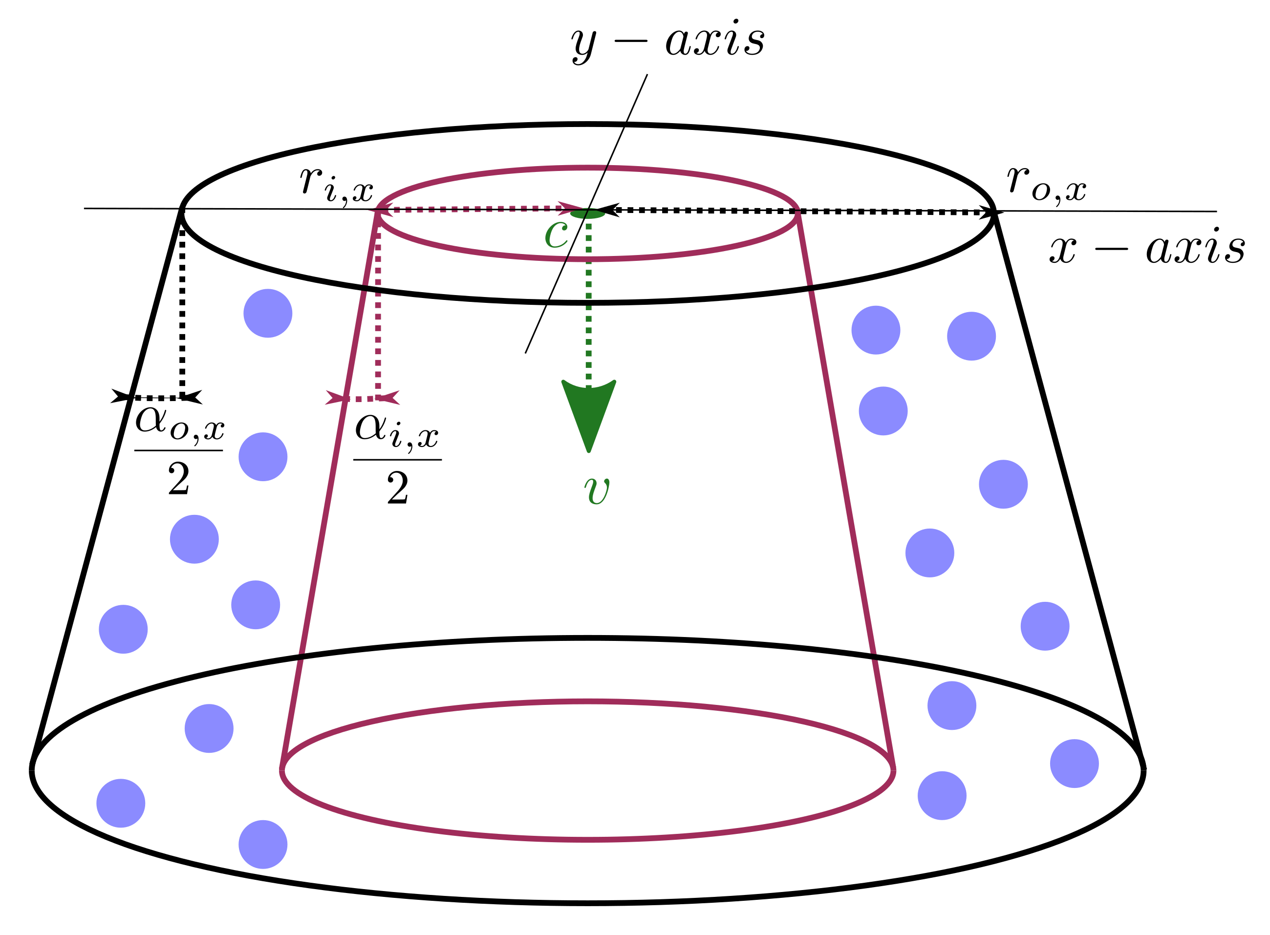
The general shape of such a spray_nozzle of shape cone or cylinder insertion can be seen here:
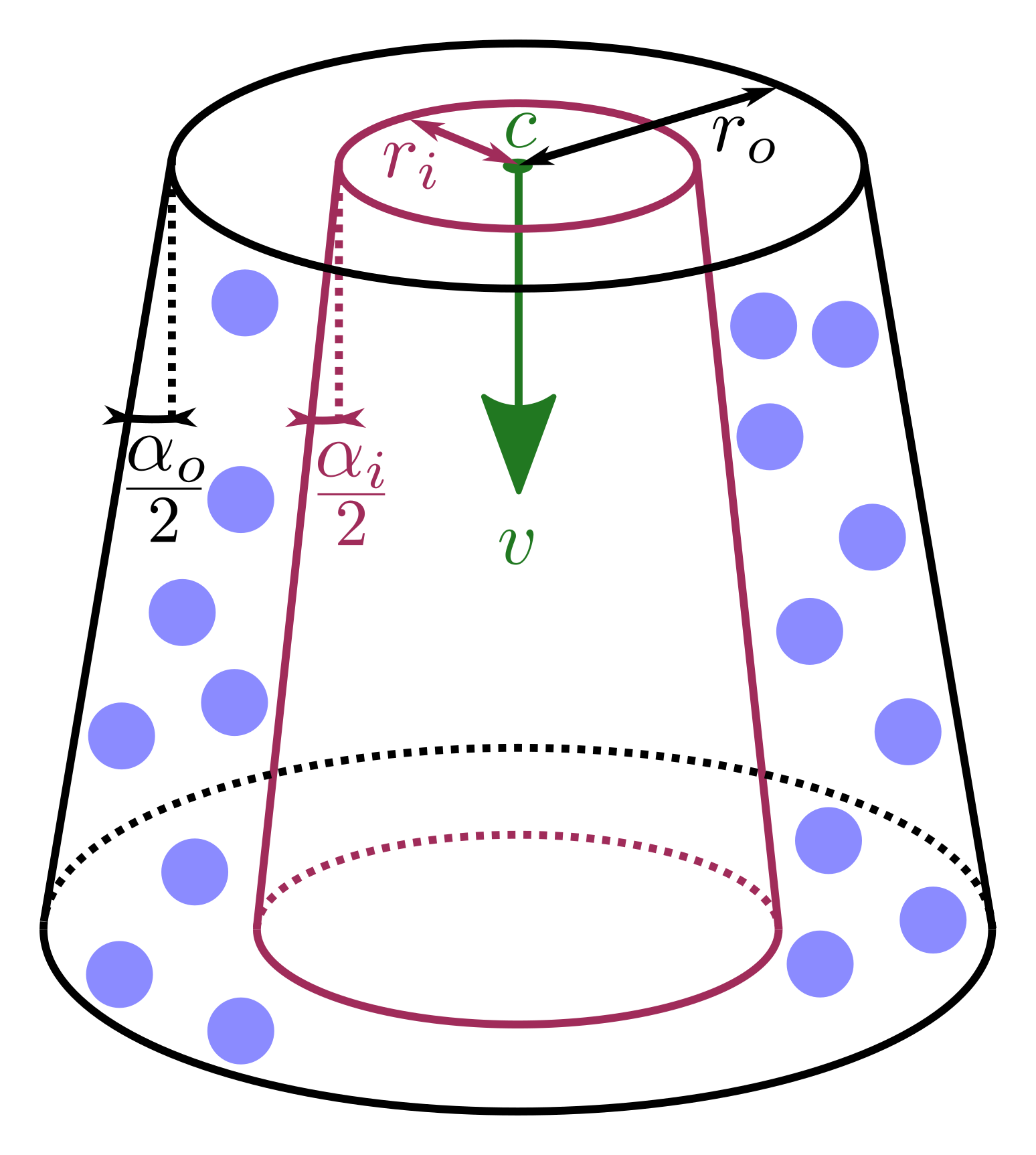
The velocity keyword specifies the vector that describes the orientation of
the nozzle and the exit velocity of the particles which is illustrated by the
green vector  above. The shape of the nozzle, specified by
nozzle_shape can be either cone or cylinder. The latter in particular is
a special case of the cone as it simply restricts outer_cone_angle and
inner_cone_angle to zero. These angles
above. The shape of the nozzle, specified by
nozzle_shape can be either cone or cylinder. The latter in particular is
a special case of the cone as it simply restricts outer_cone_angle and
inner_cone_angle to zero. These angles  and
and  can also be spotted in the image above, indicating the deviance with respect to
the orientation of the velocity vector. Note, the latter must be smaller than
the former. The particles will have a radial velocity component dependent on
where they enter the simulation domain with respect to the distance to the
center of the nozzle illustrated by the green point in the image, denoted with
can also be spotted in the image above, indicating the deviance with respect to
the orientation of the velocity vector. Note, the latter must be smaller than
the former. The particles will have a radial velocity component dependent on
where they enter the simulation domain with respect to the distance to the
center of the nozzle illustrated by the green point in the image, denoted with
 and imposed via the keyword center_of_nozzle. Finally, the outer
radius of the nozzle can be imposed via the outer_nozzle_radius keyword
(
and imposed via the keyword center_of_nozzle. Finally, the outer
radius of the nozzle can be imposed via the outer_nozzle_radius keyword
( in the image) and an optional inner radius by
inner_nozzle_radius (
in the image) and an optional inner radius by
inner_nozzle_radius ( in the image, purple). Particles will only
be inserted if they lie between the inner and outer nozzle radius, as
illustrated by the blue particles in the image.
in the image, purple). Particles will only
be inserted if they lie between the inner and outer nozzle radius, as
illustrated by the blue particles in the image.
pyramid shape
center_of_nozzle center_coordinates = (cx, cy, cz)
    cx = x-coordinate of the nozzle center (length units)
    cy = y-coordinate of the nozzle center (length units)
    cz = z-coordinate of the nozzle center (length units)
pyramid_x_axis axis_coordinates = (xx, xy, xz)
    (xx, xy, xz) = axis of one pyramid side
pyramid_x_length value = lx
    lx = length of x-axis pyramid side
pyramid_x_length value = ly
    ly = length of y-axis pyramid side
pyramid_x_angle value = alphax
    alphax = angle at pyramid side orthogonal to x-axis
pyramid_y_angle value = alphay
    alphay = angle at pyramid side orthogonal to y-axis
The general shape of such a spray_nozzle of shape pyramid insertion can be seen here:
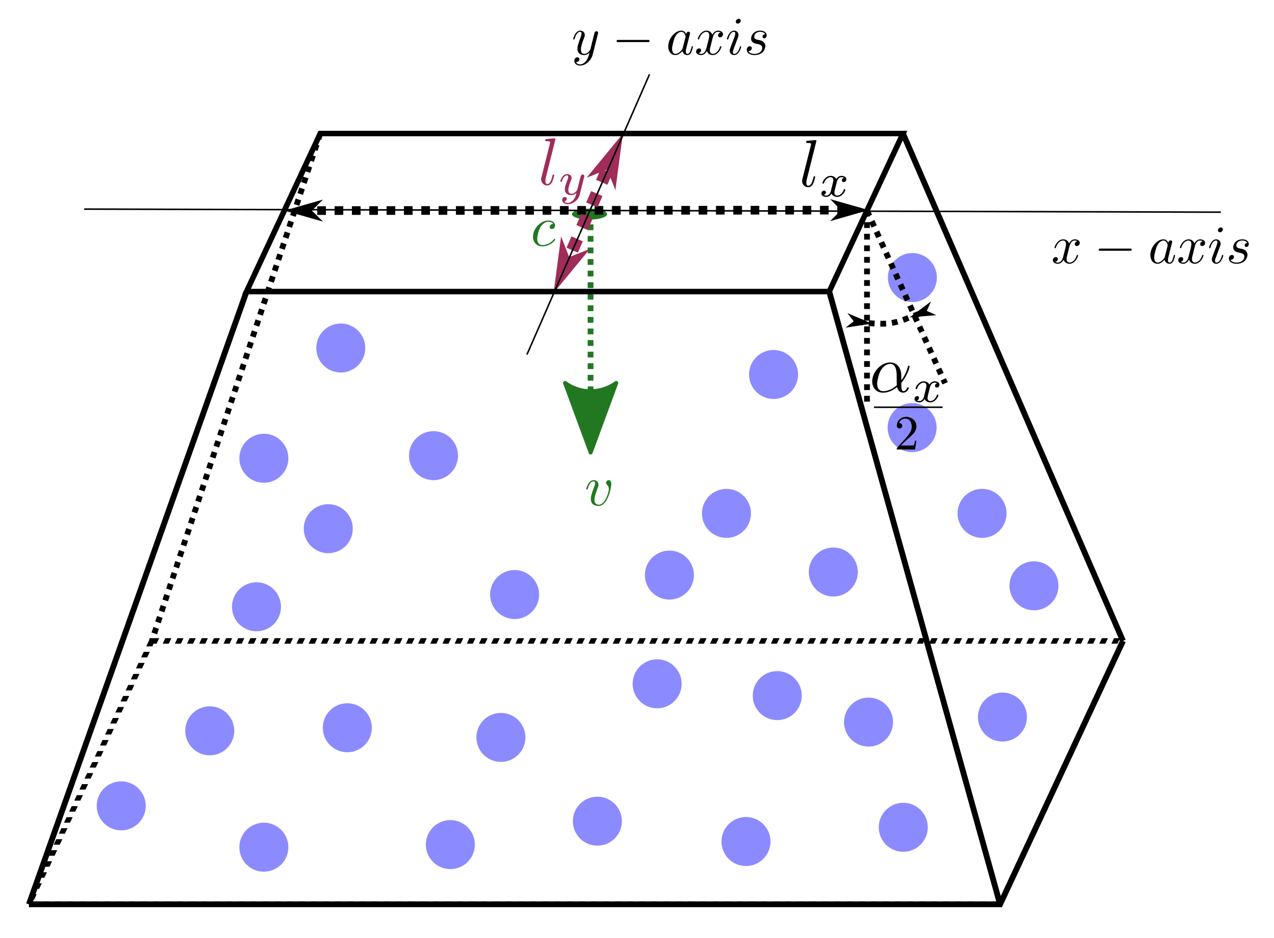
In comparison to the cone and cylinder shape an  (pyramid_x_axis) needs to be specified which is one of the pyramids principal
axis. The other axis is derived from the x-axis and the normal of the
insertion. For each principal axis the side length of the pyramid can be
specified using pyramid_x_length and pyramid_y_length. These lengths are
denoted
(pyramid_x_axis) needs to be specified which is one of the pyramids principal
axis. The other axis is derived from the x-axis and the normal of the
insertion. For each principal axis the side length of the pyramid can be
specified using pyramid_x_length and pyramid_y_length. These lengths are
denoted  and
and  in the figure above. Similarly, for each
axis an angle can be specified at the outer side of the pyramid using
pyramid_x_angle (
in the figure above. Similarly, for each
axis an angle can be specified at the outer side of the pyramid using
pyramid_x_angle ( above) and pyramid_y_angle (not shown).
nozzle_shape elliptic_cone -and- elliptic_cylinder
center_of_nozzle center_coordinates = (cx, cy, cz)
    cx = x-coordinate of the nozzle center (length units)
    cy = y-coordinate of the nozzle center (length units)
    cz = z-coordinate of the nozzle center (length units)
ellipsoid_x_axis axis_coordinates = (xx, xy, xz)
    (xx, xy, xz) = axis of a principle axis of the ellipse
outer_nozzle_x_radius value = rox
    rox = outer radius of the nozzle orifice along x-axis (positive float)
inner_nozzle_x_radius value = rix
    rix = inner radius of the nozzle orifice along x-axis (positive float and < rox)
outer_cone_x_angle value = alphaox
    alphaox = outer cone opening angle of the spray along x-axis (> 0 deg and < 180 deg)
inner_cone_x_angle value = alphaix
    alphaix = inner cone opening angle of the spray along x-axis (> 0 deg and < alphaox)
outer_nozzle_y_radius value = roy
    roy = outer radius of the nozzle orifice along y-axis (positive float)
inner_nozzle_y_radius value = ri
    riy = inner radius of the nozzle orifice along y-axis (positive float and < roy)
outer_cone_y_angle value = alphaoy
    alphaoy = outer cone opening angle of the spray along y-axis (> 0 deg and < 180 deg)
inner_cone_y_angle value = alphaiy
    alphaiy = inner cone opening angle of the spray along y-axis (> 0 deg and < alphaoy)
The general shape of such a spray_nozzle of shape elliptic_cone or elliptic_cylinder insertion can be seen here:
The elliptic shapes are pretty much identical to their circular counterparts
with the obvious difference that it also requires the specification of an
(ellipsoid_x_axis). Additionally, all parameters of the
circular counterparts have to be specified for each axis separately, e.g.
outer_cone_x_angle and outer_cone_y_angle for the outer opening angle of
the elliptic cone.
Questions?
If any questions remain, please contact us.