 Home
HomeheatTransferRadiation
Template Info
- Target Parameters: epsilon_p, Qabs_p, Qsca_p
- Contact Models: normal hertz, tangential history
- Particle Shapes: sphere
This case simulates the heat transfer in a compacted particle bed to
calibrate three parameters of the P1CFDEM radiation heat transfer model: (i)
particle emissivity epsilon_p, (ii) particle absorption efficiency Qabs_p, and (iii)
particle scattering efficiency Qsca_p. The P1CFDEM model is described in the CFDEMcoupling documentation.
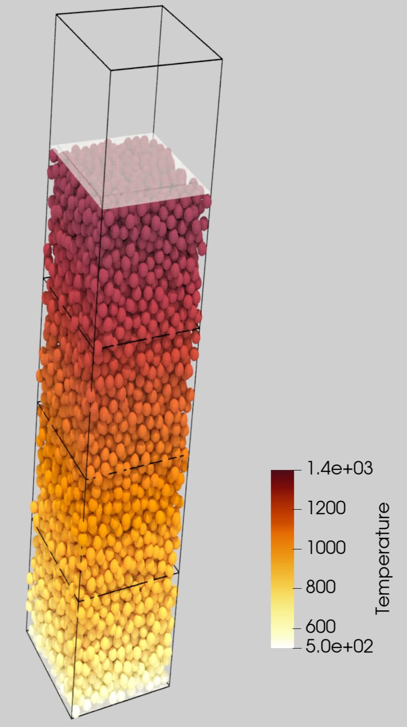
Figure 1: Simulation result obtained from heatTransferRadiation calibration
template.
Simulation phases
Initialization
During the initialization, particles are inserted into the domain
and pressed by a flat plate to form a compacted particle bed: see the illustration in the figure above.
The simulation automatically stops when the pressure in the bed reaches a certain value.
This is achieved by monitoring the time evolution of the height of the flat plate used to compress the bed, i.e.
the height of the particle bed.
Once the relative change of the height is smaller than a certain value, set by the
pressureConvTol parameter, the initialization phase is completed.
Optimization
The optimization run is a CFDEMcoupling simulation that is performed until
the effective heat transfer coefficient (see below) reaches a steady state.
A constant heat flux is imposed at the top plate, whereas a constant temperature
boundary condition is used at the bottom. The values of the top-wall heat flux and bottom-wall temperature are set by the
parameters heatFlux and T_w0, respectively.
The effective heat transfer coefficient is defined by

where  [W / m2] is the heat flux that is imposed at the top wall
,
[W / m2] is the heat flux that is imposed at the top wall
,  [m] is the compacted bed height and
  [K]
is the difference between the (calculated) averaged particle temperature and the (imposed) bottom-wall temperature.
[K]
is the difference between the (calculated) averaged particle temperature and the (imposed) bottom-wall temperature.
In fact, the region where the particle-based averaging is performed, the probe region,
can be modified by the non-dimensional parameter heatSourceFraction, which also modifies the value of
[m] used in the expression above. This parameter is a fraction of the compacted bed height
defining a distance, from the top wall
downwards, where heat transfer is imposed. Heat transfer is applied in a volume region, instead of the wall surface,
to avoid numerical issues related to particle-wall heat conduction. For example, if heatSourceFraction is set
to 0.05 (the default value), will be 0.95 times the bed height, defining a
probe region tha goes from the bottom plate up to .
The parameter heatSourceBot is used in the calculation of the probe region where the temperature averaging (measurement)
is performed. It is a fraction of the compacted bed height and it is used to define the distance from the bottom where the probe region starts.
For example, a zero heatSourceBot results in a probe region starting at the bottom wall. Non-zero values lead to
probe regions starting above the bottom wall.
The load balancing is disabled by default
due to the non-deterministic nature of the algorithm which can effect the
results of calibration. If the number of particles is sufficiently high ( and above), the non-deterministic effect induced by the load balancing algorithm
is negligible and load balancing should be enabled by setting the
parameter
and above), the non-deterministic effect induced by the load balancing algorithm
is negligible and load balancing should be enabled by setting the
parameter useLoadBalancing to 1.
Quality Function
The quality function is the percentual difference between the calculated and reference effective heat transfer coefficient:

The reference value  is set by the variable
 lambdaRef.
Measurement file
The relevant information for the calibration is the parameter
lambdaRef. However, due to current restrictions
of the framework, Aspherix® Calibration needs a measurement file to be
present. The content of this file is irrelevant and will not affect
calibration.
Template parameters
General settings
Parameter |
Default |
|---|---|
NPROC |
4 |
dumpT |
0.01 s |
dump |
0 |
useLoadBalancing |
0 |
Specific settings
Variable |
Default |
Meaning |
|---|---|---|
CG |
1.0 |
coarse graining factor |
DEMts |
1e-6 [s] |
time step of DEM simulation in the Initialization phase |
DEM_writestep |
0.001 [s] |
time step for data output of DEM simulation |
CFD_timestep |
0.002 [s] |
time step of CFD simulation |
CFD_endtime |
100.0 [s] |
maximum allowed time interval of the CFD simulation |
nCellsLength |
16 |
number of vertical CFD cells |
nCellsWidth |
4 |
number of horizontal CFD cells |
parcelsPerCell |
3 |
number of parcels per CFD cell: is used to calculate the size of the DEM simulation domain |
targetVolumeFraction |
0.65 |
insertion target volume fraction (pre-compaction) |
pressureConvTol |
1e-4 |
percentage-variation of the bed height over time during compaction: defines a steady
state criteria to stop the DEM simulation in the Initialization phase
|
servo_ctrl_Kp |
0.1 |
proportional constant
kp of the mesh_module servo for the bed compactionat the Initialzation phase (see the Aspherix Solver documentation)
|
servo_ctrl_Ki |
0.0 |
integral constant
ki of the mesh_module servo for the bed compactionat the Initialzation phase (see the Aspherix Solver documentation)
|
servo_ctrl_Kd |
0.0 |
differential constant
kd of the mesh_module servo for the bed compactionat the Initialzation phase (see the Aspherix Solver documentation)
|
servo_ctrl_max_vel |
5.0 [m / s] |
servo control PID velocity (compaction) |
heatSourceFraction |
0.05 |
fraction of the compacted bed height defining the distance, from the top wall downwards,
where heat transfer is imposed
|
probeFraction |
0.05 |
fraction of the compacted bed height defining the distance, from the bottom wall upwards,
where the particle-based temperature averaging is performed: defines the probe region
|
convergenceIters |
100 |
used to calculate the number of DEM timesteps per convergence loop in the
Optimization phase (= convergenceIters * couplingInterval)
|
convergenceRelTol |
1e-4 |
relative tolerance for lambda convergence |
couplingInterval |
10 |
used in the calculation of the DEM time step (= CFD_timestep/couplingInterval) in the optmization phase |
radiationCouplingInterval |
1 |
number of CFD timesteps per radiation solution |
radiation |
true |
switch radiation modeling on/off |
Some additional parameters have to be provided in the .casx calibration file, either as
variable, param_calibration or param_fixed. They are:
r_primary |
0.0005 [m] |
particle radius before any coarse graining is applied |
|---|---|---|
heatFlux |
10e3 [W / m2] |
heat flux applied at the top plate |
lambdaRef |
0.15 [W / (m K)] |
reference effective bed conductivity |
sigma_n |
200.0 [W / (m K)] |
compaction normal pressure [Pa] |
T_w0 |
300.0 [K] |
bottom wall temperature |
T_f0 |
300.0 [K] |
initial fluid temperature |
T_p0 |
300.0 [K] |
initial particle temperature |
absorptivity_f |
0.0 [1/m] |
fluid absorption coefficient |
emissivity_f |
0.0 [1/m] |
fluid emissivity |
emission_f |
0.0 [kg / (m s3)] |
radiation intensity emitted by the fluid |
emissivity_w |
0.8 [1/m] |
wall emissivity |
Cp_p |
1.0 [J/K] |
particle thermal capacity |
lambda_p |
0.2 [W / (m K)] |
particle thermal conductivity |
Y_p |
5e7 [Pa] |
particle Young’s Modulus |
poissons_p |
0.3 |
particle Poisson’s ratio |
rho_f |
1.2 [kg / m3] |
fluid density |
Pr_f |
0.7 |
fluid Prandtl number |
nu_f |
1.5e-5 [m / s2] |
fluid kinematic viscosity |
Some enviroment variables need to be set in order to run the CFDEMcoupling simulation: please see CFDEMcoupling intallation instructions for more details.