enable_electric_field command
Purpose
Enables use of electric field computed with CFDEMcoupling (examples).
Syntax
enable_electric_field keyword value
Keywords:
Keyword |
Description |
|---|---|
obligatory; distance up to which the near field is computed from the particles directly.
units: [length]
|
|
id |
string; user-assigned name for the command call |
particle_group |
string; group on which this command should act.
default:
all |
yes or no; if yes, particles can exchange charge during collisionsdefault:
no |
|
distance up to which charge transfer happens (see below).
default: 500 nm; or the equivalent in the chosen unit system; units: [length]
|
|
yes or no; if yes, limits force due to electric fielddefault:
no |
|
fraction of max. acceleration to be used for limiting.
default: 1e-3; range: [0,1]
|
Examples
enable_electric_field field_cutoff_radius 1e-3

enable_electric_field field_cutoff_radius 3e-3 enable_collision_charge_transfer yes

enable_electric_field field_cutoff_radius 3e-3 use_without_cfd_coupling yes
Associated material properties
Material properties
if enable_collision_charge_transfer is given, the following material parameter
needs to be given:
workFunction( ): work function of the material (energy units)
Description
Note
this command requires charged yes in your particle_shape command.
This command computes the electric field at particle positions using an approach
presented by Kolehmainen et al.. The far field is computed
on a grid, while the near field is computed directly from the particle
positions. The far field is computed using CFDEMcoupling(R): Particle charges
are mapped to a CFD grid to obtain the charge density  , then the
electric potential
, then the
electric potential  is obtained by solving Laplace’s equation

Finally, the electric far field is computed as

The near field at particle position  is computed as
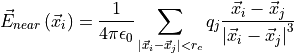
where  is the cutoff radius to be set via the
 field_cutoff_radius
keyword. This cutoff radius should be at least as large as the largest cell
diagonal in the CFD grid to make sure all particles located in the same cell are
included in the near field. This inevitably means that particles located in
other CFD cells will be included in the near field computation. To avoid them
being accounted for twice, a correction term
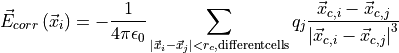
needs to be calculated. Note that
the sum only runs over particles not located in the same cell as particle

and instead of particle positions, the cell center position of particle
,  , is used (and respectively for particle
  )
)
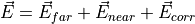
The complete field is then computed as the sum of the three components:
Charge Transfer
During each collision, charge is transfered between the collision
partners. Currently, meshes are considered grounded, conducting
walls, while primitive walls are ignored. If
particle_group is set, charge transfer only happens if both particles are
members of this group, or - for particle-wall contacts - if the
particle is in the specified group.
Charge transfer follows Kolehmainen et al.: at each time step, a charge of
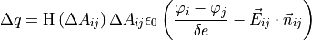
moves from particle to particle :
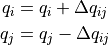
In the above equation,  is the change in contact area in
the current timestep.
is the change in contact area in
the current timestep.  is the Heaviside
function, to make sure that charge transfer only occurs as long as the contact
area increases.
is the Heaviside
function, to make sure that charge transfer only occurs as long as the contact
area increases.  ,
,  are the work functions of
both collision partners.
are the work functions of
both collision partners.  is the value for
charge_transfer_cutoff, and  is the elementary charge (positive
value). The last term adds the influence of the electric field:
is the elementary charge (positive
value). The last term adds the influence of the electric field:
 is the electric field at the collision point, and
 is a unit vector from particle to
. Dielectric breakdown (rapid redistribution of charges due to a
sufficiently large electric field) is currently not included in this model.
is a unit vector from particle to
. Dielectric breakdown (rapid redistribution of charges due to a
sufficiently large electric field) is currently not included in this model.
Stability Enhancement
To increase the stability of a simulation, the setting limit_field_force can
be used.
If activated, limit_field_force limits the force a particle experiences due to
the total electric field it sees. This can be useful if the initial condition of
a simulation is unphysical. A very basic criterion for stability is that a
particle does not travel further than the skin distance in a single time
step. This is satisfied if
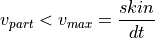
with  being the skin distance set through the neighbor_list command, and
  the simulation timestep. A force
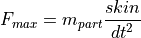
would accelerate a particle of mass  from rest to
 in a single timestep.
 limit_field_force limits the force
coming from the electric field to
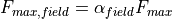
where  is a tunable factor which can be set
through
is a tunable factor which can be set
through field_force_limit_factor.
Restrictions
An enable_cfd_coupling command must appear before
this command, unless explicitly deactivated via use_without_cfd_coupling.
There can only be one enable_electric_field command in the
whole simulation.